Fixing device for new energy automobile battery pack box frame and automatic welding system

A technology for new energy vehicles and fixtures, applied in welding equipment, auxiliary equipment, auxiliary welding equipment, etc., can solve problems such as easy deformation, and achieve the effect of reducing the possibility of deformation and facilitating installation

Active Publication Date: 2022-01-28
江苏铭智新能源汽车零部件有限公司
View PDF5 Cites 0 Cited by
  • Summary
  • Abstract
  • Description
  • Claims
  • Application Information

AI Technical Summary

Problems solved by technology

[0005] In order to improve the problem that the box frame is easily deformed during welding, this application provides a fixing device for the box frame of the new energy vehicle battery pack and an automatic welding system

Method used


Image

  • Fixing device for new energy automobile battery pack box frame and automatic welding system
  • Fixing device for new energy automobile battery pack box frame and automatic welding system
  • Fixing device for new energy automobile battery pack box frame and automatic welding system

Examples


Embodiment 1

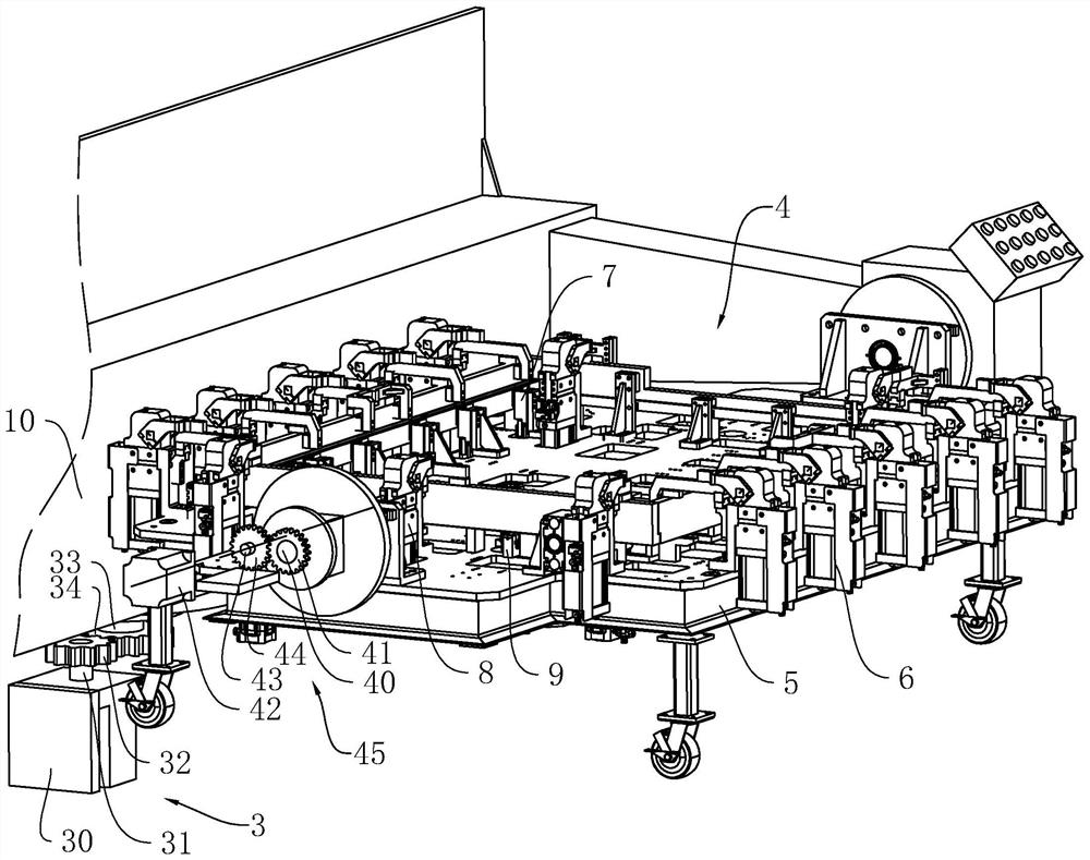
[0061] refer to figure 1 with figure 2 , a new energy vehicle battery pack box frame fixing device and automatic welding system, including a base 1 and a welding robot 12 for welding the box frame, the welding robot 12 is arranged on one side of the base 1, and the base 1 is provided with The turret 10, the base 1 is provided with a power unit 3 that drives the turret 10 to rotate horizontally, the turret 10 is provided with a fixing device 4, the number of the fixing devices 4 is two, and the two fixing devices 4 are arranged oppositely. A partition 11 for separating the two fixing devices 4 is provided, which can reduce the possibility of scalding workers caused by welding sparks.

[0062] refer to figure 1 with figure 2 , the turret 10 is provided with a drive unit 45 for driving the fixture 4 to turn over; when welding is required, the drive unit 45 drives the fixture 4 to turn over to be a vertical device, and the workman will first set of crossbars, beams, vertical ...

Embodiment 2

[0083] refer to Figure 9 , The difference between this embodiment and Embodiment 1 is that it also includes a feeding device 2; Assemblies 21 , the frame 20 is provided with a conveying assembly 22 for conveying crossbars and beams, and the frame 20 is provided with a picking assembly 23 for moving the crossbars and beams from the output assembly 21 to the conveying assembly 22 .

[0084] refer to Figure 9 , the frame 20 is provided with a clamping assembly 24 for mounting the cross bar and the beam on the fixture 4, the clamping assembly 24 is located between the conveying assembly 22 and the fixture 4, and the frame 20 is provided with a clamping assembly 24 for mounting the longitudinal bar The moving assembly 25 installed on the fixing device 4 with the longitudinal beam, the moving assembly 25 is located between the output assembly 21 and the fixing device 4 .

[0085] refer to Figure 9 with Figure 10 , the conveying assembly 22 includes a conveying motor 220 arra...


PUM


Abstract

The invention relates to a fixing device for a new energy automobile battery pack box frame and an automatic welding system, and relates to new energy automobile accessory machining equipment, the fixing device comprises a bottom frame, the bottom frame is provided with a fixing assembly used for fixing a cross rod and a cross beam, and the bottom frame is provided with an abutting assembly used for pressing the cross rod; and the bottom frame is provided with a positioning assembly used for fixing longitudinal rods and longitudinal beams, and the bottom frame is provided with a pressing assembly used for fixing the longitudinal rods. The fixing device has the beneficial effects that the working mode of manual supporting of workers can be replaced, the possibility of deflection between workpieces is reduced, and the possibility of deformation of a new energy automobile battery pack box body frame is reduced advantageously.

Description

technical field [0001] The present application relates to a processing equipment for new energy automobile parts, in particular to a fixing device and an automatic welding system for the frame of a battery pack box of a new energy automobile. Background technique [0002] The battery pack is the power battery, which is a power source that provides the power source for vehicles. The vehicles mostly refer to electric vehicles, electric trains, electric bicycles, golf carts, etc. The battery pack is usually installed on the frame of the battery pack case. [0003] The existing box frame includes a cross bar and a cross beam, the cross bar and the cross beam are arranged oppositely, a longitudinal bar and a longitudinal beam are arranged between the cross bar and the cross beam, the longitudinal bar and the longitudinal beam are arranged oppositely, the box frame is a rectangular frame, The lengths of the cross bars and the beams are greater than the lengths of the longitudinal...

Claims


Application Information

Patent Timeline
IPC IPC(8): B23K37/02B23K37/04H01M50/244H01M50/249
CPCB23K37/02B23K37/0443H01M50/244H01M50/249Y02E60/10
Inventor 赵如意黄颖耀陈海斌
Owner 江苏铭智新能源汽车零部件有限公司
Why Eureka
Try Eureka