
Circuit board and manufacturing method thereof

A production method and circuit board technology, which is applied in multi-layer circuit manufacturing, printed circuit manufacturing, printed circuit, etc., can solve the problems of high window opening precision, difficult removal of machine flow glue, and high molding size requirements, etc., to achieve reduction Difficulty in production and the effect of reducing the mixing of foreign matter

Pending Publication Date: 2022-01-21
HONG HENG SHENG ELECTRICAL TECH HUAIAN +1
View PDF0 Cites 0 Cited by
  • Summary
  • Abstract
  • Description
  • Claims
  • Application Information

AI Technical Summary

Problems solved by technology

However, this method has high requirements for the size of the copper block and the molding size. During the pressing process, the window needs to be opened in alignment, and the precision of the window opening is high, and the organic flow glue is difficult to remove after pressing and filling.

Method used


Image

  • Circuit board and manufacturing method thereof
  • Circuit board and manufacturing method thereof
  • Circuit board and manufacturing method thereof

Examples


Embodiment Construction

[0058] The following description will refer to the accompanying drawings in order to describe the present disclosure more fully. Exemplary embodiments of the invention are shown in the drawings. This invention may, however, be embodied in many different forms and should not be construed as limited to the exemplary embodiments set forth herein. Rather, these exemplary embodiments are provided so that this disclosure will be thorough and complete, and will fully convey the scope of the invention to those skilled in the art. Like reference numerals designate the same or similar components.

[0059] The terminology used herein is for the purpose of describing particular exemplary embodiments only and is not intended to be limiting of the invention. As used herein, the singular forms "a", "an" and "the" are intended to include the plural forms as well, unless the context clearly dictates otherwise. Furthermore, when used herein, "comprises" and / or "comprises" or "includes" and / o...


PUM


Abstract

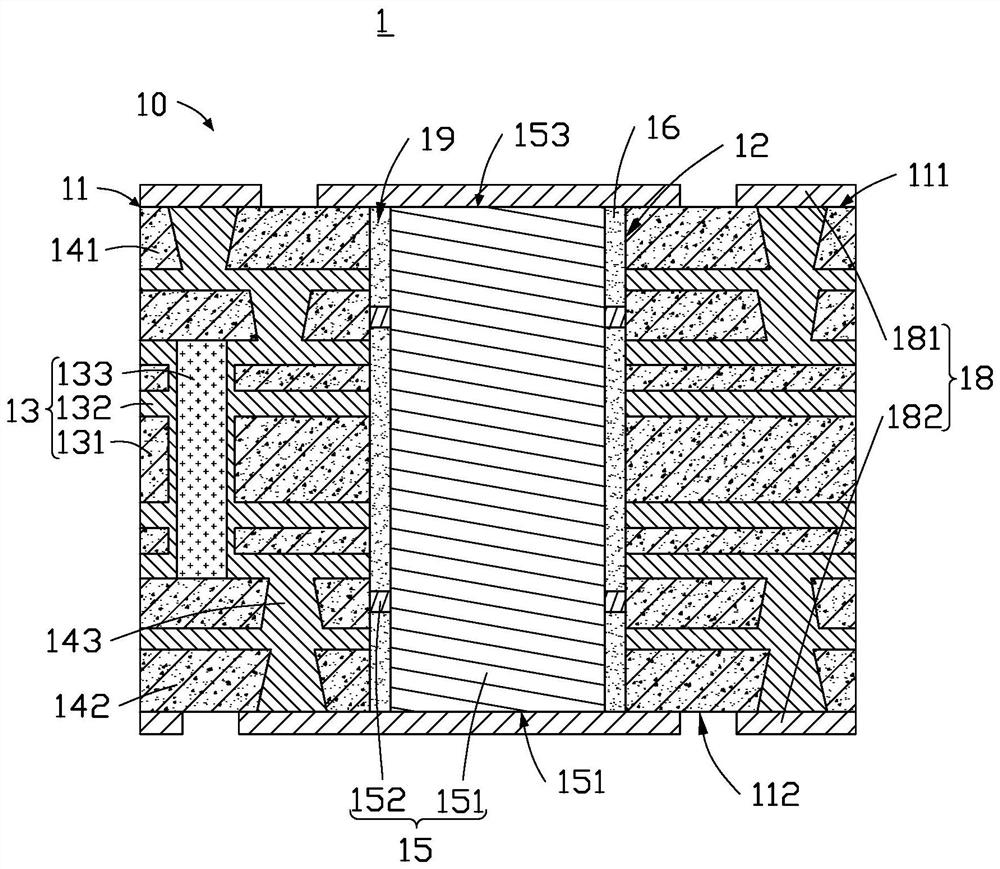
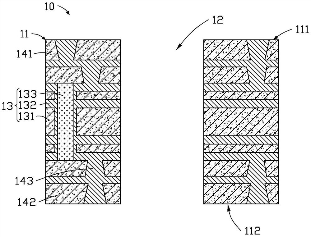
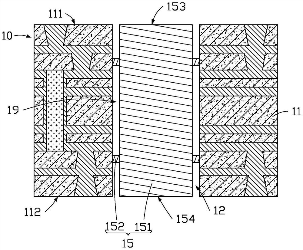
The invention provides a circuit board, which comprises: a circuit stack-up structure comprising a first main body part and a through groove arranged on the first main body part in a penetrating manner; a heat dissipation unit arranged in the through groove, wherein the heat dissipation unit comprises a second main body part and a pin, and the second main body part is clamped with the first main body part through the pin; and a filling unit arranged between the first main body part and the second main body part. The invention further provides a manufacturing method of the circuit board.

Description

technical field [0001] The invention relates to the technical field of circuit boards, in particular to a circuit board and a manufacturing method thereof. Background technique [0002] Optical fiber connector is an important component to realize the connection between electronic products and optical fiber network. The optical fiber connector includes a circuit board, and the circuit board is used as the carrier of electronic devices to connect electronic components to each other. In the optical fiber connector, the conversion between electrical signals and optical signals is realized through the driver chip. However, a large amount of heat energy will be generated during the conversion process, and the heat will cause the internal temperature of the components to rise rapidly. Requirements, it is necessary to use an additional heat dissipation unit (such as a metal block) to assist heat dissipation. [0003] In order to solve this problem, the industry usually forms an inn...

Claims


Application Information

Patent Timeline
IPC IPC(8): H05K1/02H05K3/46
CPCH05K1/0204H05K3/4697H05K2201/06
Inventor 周剑波
Owner HONG HENG SHENG ELECTRICAL TECH HUAIAN
Learn More