
Compact independent power supply remote control trigger

A technology of remote control and independent power supply, which is applied in the direction of electric pulse generator circuits, electrical components, circuit devices, etc., to achieve the effects of enhancing anti-interference ability, realizing protection and realizing miniaturization

Pending Publication Date: 2022-01-21
CSSC SYST ENG RES INST
View PDF0 Cites 0 Cited by
  • Summary
  • Abstract
  • Description
  • Claims
  • Application Information

AI Technical Summary

Problems solved by technology

[0004] The embodiment of the present invention provides a portable, independent power supply, remote control low-cost, short trigger delay, small jitter, fast front, strong anti-interference ability, to overcome the contradiction between portability and high performance in the existing field test The defective compact independently powered remote control trigger

Method used


Image

  • Compact independent power supply remote control trigger
  • Compact independent power supply remote control trigger
  • Compact independent power supply remote control trigger

Examples


Embodiment Construction

[0034] In order to enable those skilled in the art to better understand the technical solutions of the present invention, the present invention will be further described below in conjunction with the accompanying drawings and specific embodiments.

[0035] In this specification the phrases "in one embodiment", "in another embodiment", "in a further embodiment", "in an embodiment", "in some embodiments" or "In other embodiments" may refer to one or more of the same or different embodiments according to the present invention.

[0036] Specific embodiments of the present invention are hereinafter described with reference to the accompanying drawings; however, it should be understood that the disclosed embodiments are merely embodiments of the invention, which may be implemented in various ways. Well-known and / or repeated functions and structures are not described in detail to ascertain the true intention based on the user's historical operations, and to avoid obscuring the presen...


PUM

PropertyMeasurementUnit
Amplitudeaaaaaaaaaa
Amplitudeaaaaaaaaaa

Abstract

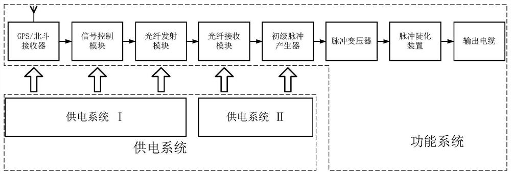
The embodiment of the invention provides a compact independent power supply remote control trigger comprising a GPS / Beidou receiver used for receiving a remote control signal and outputting a control signal, a signal control module used for conditioning the control signal and generating a first level signal, an optical fiber transmitting module used for receiving the first level signal and outputting an optical pulse after electro-optical conversion, an optical fiber receiving module used for receiving the optical pulse, performing photoelectric conversion and outputting a second level signal, a primary pulse generator used for receiving the second level signal and generating a medium-voltage pulse signal through an internal medium-voltage discharge circuit, a pulse transformer used for converting the medium-voltage pulse signal into a high-voltage pulse signal, a pulse steepening device used for receiving the high-voltage pulse signal and realizing steepening of the leading edge of the high-voltage pulse signal, and an output cable used for realizing trigger control on the high-voltage switch based on the steepened high-voltage pulse signal of the leading edge.

Description

technical field [0001] The invention relates to the technical field of triggers, in particular to a compact independent power supply remote control trigger. Background technique [0002] Pulse power systems usually use high-voltage pulses with fast front edges to control the conduction of switches and form discharges. The technical principles of the trigger mainly include capacitor discharge, transmission line voltage doubling and pulse transformer step-up, all of which adopt a hierarchical structure, and the voltage pulse is gradually amplified from the volt level to tens of kilovolts or even hundreds of kilovolts. [0003] The current flip-flops are mainly divided into capacitor fast discharge type, mini-Marx type, pulse transformer type, transmission line type and Pichugin type. Capacitor fast-discharge type triggers are simple in structure and mature in technology, but have a high probability of misfiring; mini-Marx type and pulse transformer type triggers have large sy...

Claims


Application Information

Patent Timeline
IPC IPC(8): H02J13/00H03K3/57
CPCH02J13/00022H02J13/00017H02J13/00036H03K3/57Y02E60/00Y04S40/126Y04S40/124
Inventor 周海滨张文译王一帆陈骁卢得龙王国庆金素宇
Owner CSSC SYST ENG RES INST
Learn More