Eureka AIR delivers breakthrough ideas for toughest innovation challenges, trusted by R&D personnel around the world.

Bolt torque detection device

A technology for torque detection and bolts, which is applied in the field of bolt torque detection devices, can solve problems such as inconvenient carrying, heavy weight, and impact on detection efficiency, so as to improve the range of position and angle adjustment, ensure flexibility, and reduce the risk of personal injury Effect

Pending Publication Date: 2022-01-21
SGIS SONGSHAN CO LTD
View PDF0 Cites 0 Cited by
  • Summary
  • Abstract
  • Description
  • Claims
  • Application Information

AI Technical Summary

Problems solved by technology

It has a certain impact on the detection efficiency, and because it is made of metal, it is heavy and inconvenient to carry

Method used


Image

  • Bolt torque detection device
  • Bolt torque detection device
  • Bolt torque detection device

Examples


Embodiment 1

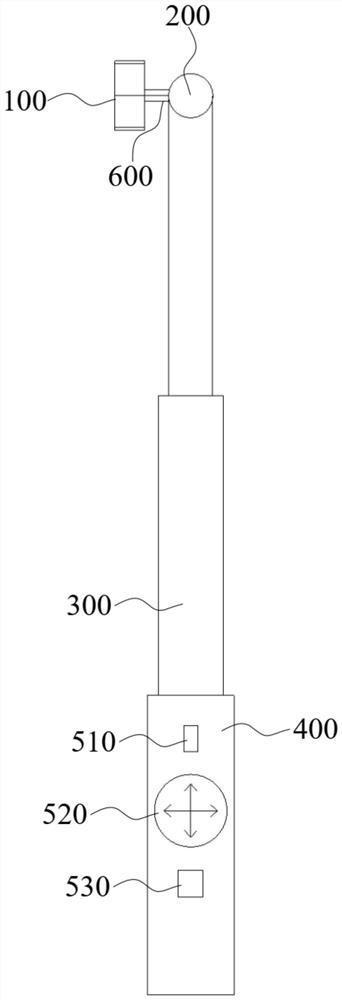
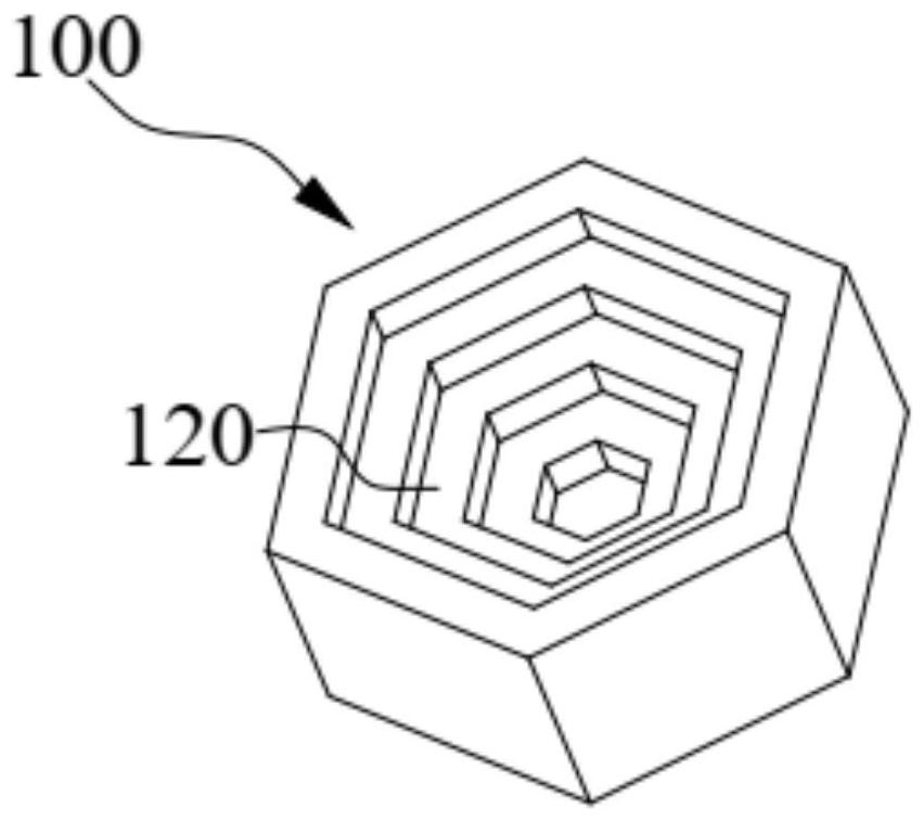
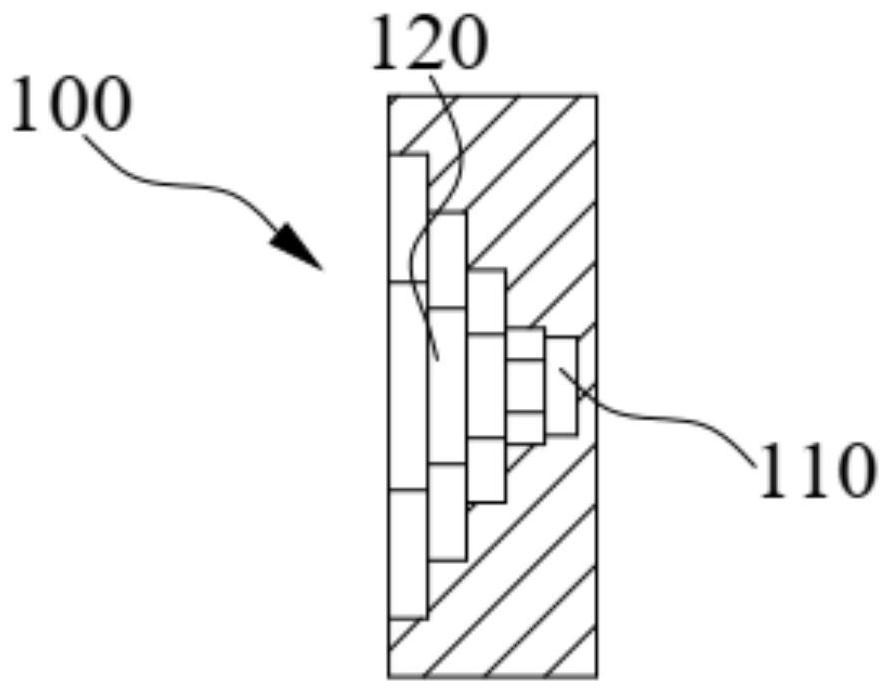
[0030] Such as Figure 1-Figure 3 As shown, the present embodiment provides a bolt torque detection device for testing the fastening performance of bolts, including a positioning fixture 100, a handle part 400 and a control panel; the positioning fixture 100 is a cylindrical part, and the positioning fixture 100 One side of the limit groove is provided with a limit groove, which can be sleeved on the nut of the bolt, and the bottom of the limit groove is also provided with an adsorption piece 110, which is used to absorb the bolt; the handle piece 400 is connected to the multi-stage telescopic rod 300 At one end, the end of the multi-stage telescopic rod 300 away from the handle part 400 is rotationally connected with the side of the positioning fixture 100 that is not provided with a limit groove through a universal joint 200; the control panel is installed on the handle part 400, and the control panel can control the multi-stage telescopic rod 300 telescopic, the positioning...

Embodiment 2

[0044] Such as Figure 4 As shown, the bolt torque detection device of the second embodiment is basically the same as the first embodiment above, the difference between the two is that a plurality of abutting pieces 140 are arranged in the limiting groove, and the abutting pieces 140 can abut against the nuts. On the side, the abutment piece 140 is connected with a telescopic piece 130, and the telescopic piece 130 can drive the abutment piece 140 to approach or move away from the middle of the limiting groove. The arrangement of the abutting piece 140 ensures that the positioning fixture 100 can be widely used in the detection of various sizes and types of bolts, thereby greatly improving the detection efficiency.

[0045] Specifically, the positioning jig 100 further includes a third driving unit, the third driving unit is used to drive the telescopic member 130 to expand or contract, and the third driving unit is disposed in the positioning jig 100 .

[0046] In this embod...


PUM


Abstract

The invention relates to the technical field of structure detection, and particularly discloses a bolt torque detection device. The device is used for testing the fastening performance of a bolt and comprises a positioning clamp, a handle piece and a control panel; the positioning clamp is a cylindrical part, a limiting groove is formed in one side of the positioning clamp, a nut of the bolt can be sleeved with the limiting groove, and an adsorption part is further arranged at the bottom of the limiting groove and used for adsorbing the bolt; the handle piece is connected with one end of the multi-stage telescopic rod, and the end, away from the handle piece, of the multi-stage telescopic rod is rotationally connected with the side, without the limiting groove, of the positioning clamp through a universal joint; the control panel is installed on the handle piece and can control the multi-stage telescopic rod to stretch out and draw back, and the positioning clamp can rotate along the axis of the positioning clamp and can rotate relative to the multi-stage telescopic rod. According to the device, through the structural design that the position and the angle of the positioning fixture are adjustable, the detection of the fastening performance of the bolt can be accurately completed, and the detection efficiency is improved while the detection safety is ensured.

Description

technical field [0001] The invention relates to the technical field of structure detection, in particular to a bolt torque detection device. Background technique [0002] For the detection of steel structure buildings, the inspection of the bolt fastness of the joint joints is an important detection content, especially for high-strength bolts, this detection is more important. For example, in the inspection process of a factory building with a crane, since the detection position of the high-strength bolts longitudinally connected between the crane girders is far away, it is difficult to inspect the bolt fastening directly by hand or with a handheld instrument, especially in the crane There is one side of the sliding wire, which is easy to cause electric shock and cause serious injury such as electric shock to the testing personnel. Since the distance between the crane girder and the ground is generally far (generally, the vertical distance is greater than 20 meters), improp...

Claims


Application Information

Patent Timeline
Patent Type & Authority Applications(China)
IPC IPC(8): G01L5/24
CPCG01L5/24
Inventor 钟鸽荘曾涛米保军周永椗王宏平袁泉江叶碧菁彭岗程坤胡晓宇吴恩茹赖妮丝
Owner SGIS SONGSHAN CO LTD
Why Eureka
Eureka Blog
Learn More