Kitchen garbage pretreatment collecting device

A collection device and kitchen waste technology, applied in grain processing, presses, manufacturing tools, etc., can solve problems such as low efficiency, difficult handling, and odors in storage locations

Inactive Publication Date: 2022-01-21
徐永祥
View PDF0 Cites 0 Cited by
  • Summary
  • Abstract
  • Description
  • Claims
  • Application Information

AI Technical Summary

Problems solved by technology

[0003] At present, most of the kitchen waste treatment methods on the market are mainly through artificially sorting and packing the kitchen waste and sending them to the garbage point. In the process, it bears more weight, and it needs to be collected manually, and the storage location will have a large odor, or it can be equipped with a device that can squeeze and crush kitchen waste, but the general extrusion and centrifugal The dehydration method is not efficient, or it can be equipped with a spiral dehydration device, but it is impossible to observe whether the dehydration operation of the device is normal from the outside, making it impossible to correct the device in time, and the amount of water discharged from each part is inconsistent. It is impossible to control the air flow of pumping water according to the amount of water. The above situation will lead to a large amount of water, difficult handling, manual collection and treatment, large odor, inefficient dehydration method, inability to observe whether the device is working normally, and failure to timely Correction of the device and the problem of not being able to control the size of the airflow for pumping water according to the amount of water

Method used


Image

  • Kitchen garbage pretreatment collecting device
  • Kitchen garbage pretreatment collecting device
  • Kitchen garbage pretreatment collecting device

Examples


Embodiment

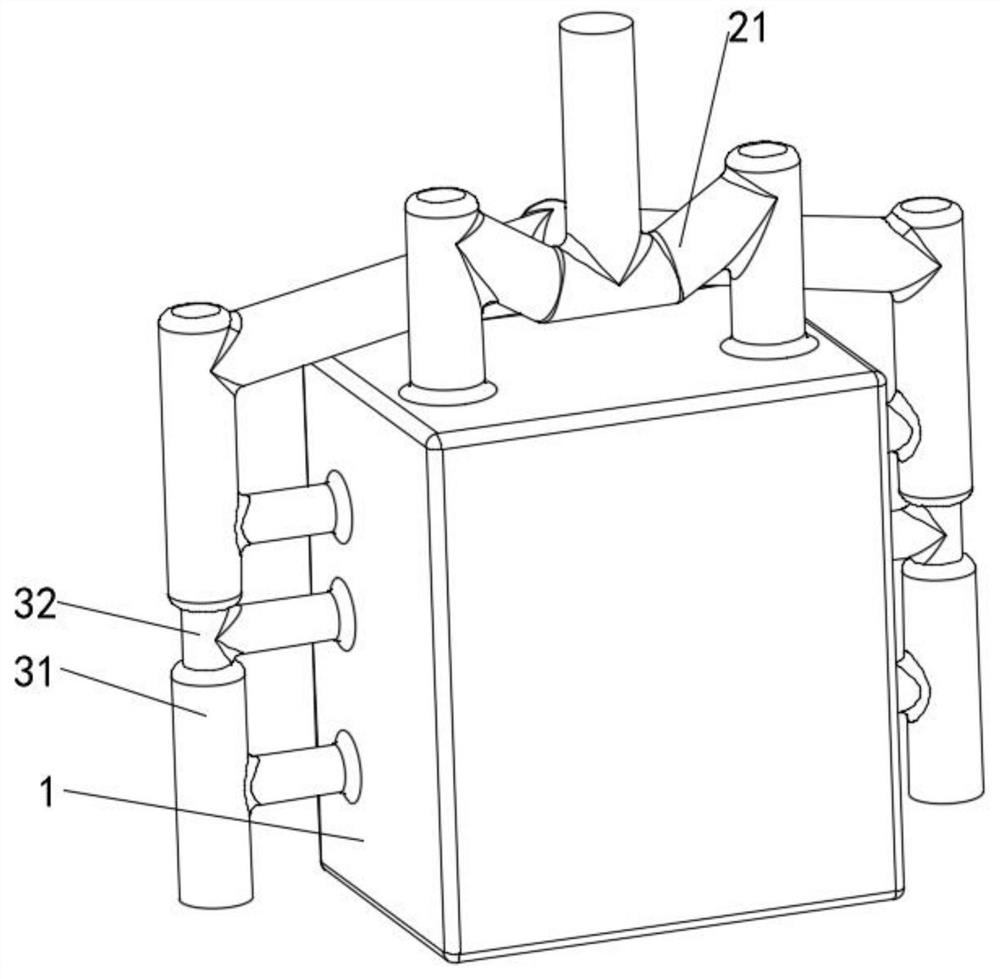
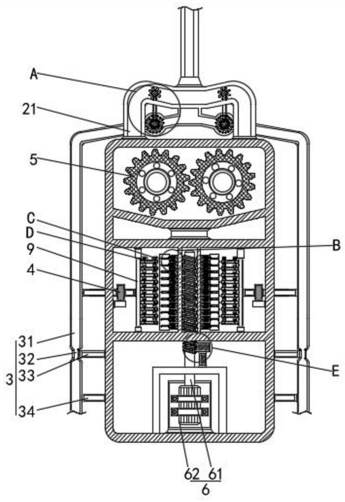
[0029] see Figure 1-7 , a pretreatment collection device for kitchen waste, comprising a box body 1, a feed assembly 2 is fixedly connected to the upper side of the box body 1, a connection assembly 3 is fixedly connected to the rear side of the feed assembly 2, and the inner side of the box body 1 The drive assembly 6 is fixedly connected, and the left and right sides of the drive assembly 6 are provided with a display assembly 7, and the outside of the display assembly 7 is provided with a detection assembly 8. The detection assembly 8 includes a flow channel 81, and the inner side of the flow channel 81 is slidably connected with a floating ball. The right side of the rod 82 and the float rod 82 is fixedly connected with a paddle 83, and the right side of the paddle 83 is slidably connected with a sliding rheostat 84.

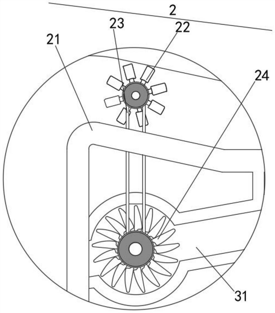
[0030] Further, the feed assembly 2 includes a feed pipe 21 fixedly connected to the box body 1, the inner side of the feed pipe 21 is rotatably connected ...


PUM


Abstract

The invention discloses a kitchen garbage pretreatment collecting device. The device comprises a box body, the upper side of the box body is fixedly connected with a feeding assembly, the rear side of the feeding assembly is fixedly connected with a connecting assembly, the inner side of the box body is fixedly connected with a driving assembly, and the left side and the right side of the driving assembly are each provided with a display assembly. A detection assembly is arranged at the outer side of each display assembly and comprises a flow channel, a floating ball rod is slidably connected to the inner side of each flow channel, a shifting piece is fixedly connected to the right side of each floating ball rod, and a slide rheostat is slidably connected to the right side of each shifting piece. According to the kitchen garbage pretreatment collecting device, the floating ball rods are driven to move upwards through the buoyancy effect, so that the shifting pieces are driven to slide upwards on the slide rheostats, the resistance value in the slide rheostats is changed, the current of a coil can be changed, and then the opening size of magnetic rods and the flow channels is controlled; and by means of the structure, the purposes that the water pumping airflow can be controlled according to the water amount, and the water pumping efficiency is high are achieved.

Description

technical field [0001] The invention relates to the technical field of advanced environmental protection industry, in particular to a pretreatment collection device for kitchen waste. Background technique [0002] With the continuous development of society, people's awareness of environmental protection has been continuously strengthened. Nowadays, many cities have implemented environmental protection measures for garbage classification, among which the classification of kitchen waste is relatively difficult. [0003] At present, most of the kitchen waste treatment methods on the market are mainly through artificially sorting and packing the kitchen waste and sending them to the garbage point. In the process, it bears more weight, and it needs to be collected manually, and the storage location will have a large odor, or it can be equipped with a device that can squeeze and crush kitchen waste, but the general extrusion and centrifugal The dehydration method is not efficient...

Claims


Application Information

Patent Timeline
IPC IPC(8): B02C4/28B02C4/08B02C23/00B30B9/02B30B9/12B30B15/00B30B15/32
CPCB02C4/286B02C4/08B02C23/00B30B9/12B30B9/125B30B9/02B30B15/00B30B15/32B02C2201/06
Inventor 徐永祥
Owner 徐永祥
Why Eureka
Try Eureka