Water tank garbage automatic desalting and water separating device

A garbage and sink technology, applied in water supply installations, indoor sanitary pipe installations, buildings, etc., can solve the problems of clogging and cleaning of drains, pollution of the surrounding environment, clogging of drains, etc., to achieve convenient use, reduce labor intensity, and improve efficiency. and the effect of the effect

Inactive Publication Date: 2020-06-19
上海格领环保科技有限公司
View PDF3 Cites 0 Cited by
  • Summary
  • Abstract
  • Description
  • Claims
  • Application Information

AI Technical Summary

Problems solved by technology

[0003] Household sinks are the main sources of wet waste (biomass waste). The traditional design scheme is to install a wet waste barrier filter in the sink to prevent waste from flowing into the sewer and causing blockage. In actual use, such a barrier filter There are many problems in the net scheme, such as the existing barrier filter is easy to cause poor water flow, and sometimes even block the drain; moreover, the existing sink will produce oil stains and other pollution during use, which not only easily causes the drain to block but also blocks the drain. It is difficult to clean up at times, and the accumulated garbage is more likely to be flushed into the sewer; moreover, after the garbage is blocked by the blocking filter in the existing sink, it is necessary to manually take out the garbage blocked by the blocking filter from the sink and put it into the garbage bin for collecting wet garbage , the process is not only cumbersome, but also often causes pollution to the surrounding environment during the process of moving garbage

Method used


Image

  • Water tank garbage automatic desalting and water separating device
  • Water tank garbage automatic desalting and water separating device
  • Water tank garbage automatic desalting and water separating device

Examples


Embodiment Construction

[0026] In order to make the technical means, creative features, goals and effects achieved by the present invention easy to understand, the present invention will be further described below in conjunction with specific illustrations.

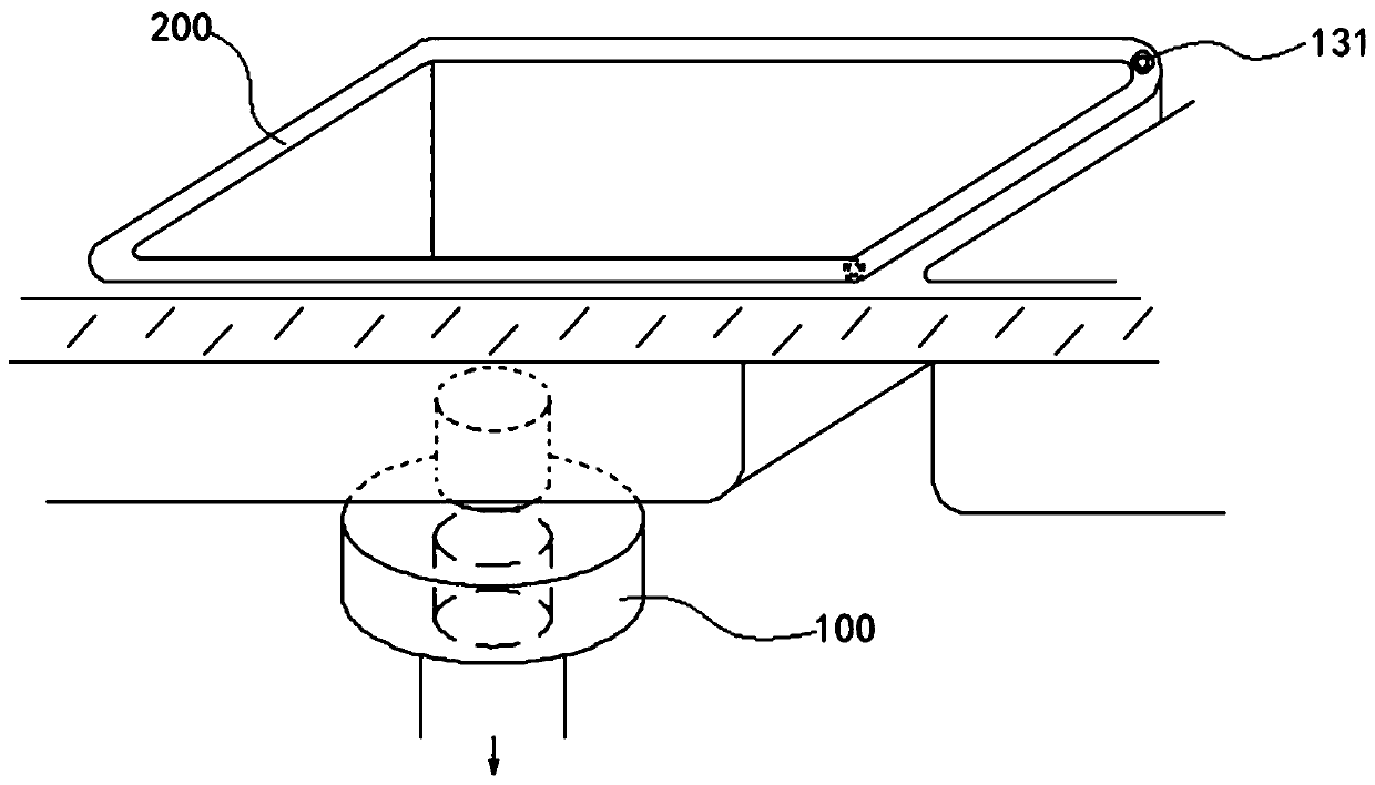
[0027] see figure 1 , this example aims at the structure of the existing water tank, and presents a scheme of automatic garbage water cutting device 100 for the water tank, which can be conveniently connected with the drain of the water tank 200 without changing the structure and usage of the existing water tank With cooperation, the garbage and water directly discharged from the sink 200 through the drain can be cut and treated, the garbage and water can be separated, and the separated garbage can be automatically collected, which greatly improves the efficiency and effect of wet garbage (biomass garbage) collection and treatment , and the whole process does not require manual intervention, and the operation is convenient, which greatly reduces...


PUM


Abstract

The invention discloses a water tank garbage automatic desalting and water separating device. The water tank garbage automatic desalting and water separating device comprises a garbage temporary storage unit and a water separating unit, wherein a garbage temporary storage cavity is formed in the garbage temporary storage unit, a feeding port, a drainage port and a discharging port are arranged onthe garbage temporary storage cavity, the feeding port can communicate with the drainage port of a water tank, a water separating net is arranged at the drainage port in the garbage temporary storagecavity, a water separating assembly in the water separating unit is movably arranged in the garbage temporary storage cavity of the garbage temporary storage unit, the movement stroke of the water separating assembly matches with the drainage port and the discharging port in the garbage temporary storage cavity, and a driving assembly in the water separating unit drives the water separating deviceto act in the garbage temporary storage cavity, so that garbage in the garbage temporary storage cavity moves towards the discharging port. The device can be connected and matches with an existing water tank, the garbage discharged through the water tank can be automatically desalted and subjected to water separating, solid-liquid separation of the garbage is achieved, peculiar smells are effectively prevented from being emitted from the water tank, the separated garbage is automatically collected, and the efficiency and effect of the wet garbage collection and treatment are greatly improved.

Description

technical field [0001] The invention relates to a garbage treatment scheme, in particular to a garbage treatment technology in a domestic water tank. Background technique [0002] Under the background of promoting waste reduction (source self-care, resource utilization) in the whole society, how to make resource utilization of wet waste (biomass waste) is the most important problem facing society today. [0003] Household sinks are the main sources of wet waste (biomass waste). The traditional design scheme is to install a wet waste barrier filter in the sink to prevent waste from flowing into the sewer and causing blockage. In actual use, such a barrier filter There are many problems in the net scheme, such as the existing barrier filter is easy to cause poor water flow, and sometimes even block the drain; moreover, the existing sink will produce oil stains and other pollution during use, which not only easily causes the drain to block but also blocks the drain. It is diff...

Claims


Application Information

Patent Timeline
Patent Type & Authority Applications(China)
IPC IPC(8): E03C1/264
CPCE03C1/264
Inventor 陈桂林
Owner 上海格领环保科技有限公司
Why Eureka
Try Eureka