Portable turnout operation device and turnout operation method
An operating device and portable technology, which are applied to electrical equipment, transportation and packaging, railway car body parts, etc. for manipulating turnouts or line circuit breakers. Large volume and other problems, to achieve the effect of easy on-site portability, light structure, and few components
- Summary
- Abstract
- Description
- Claims
- Application Information
AI Technical Summary
Problems solved by technology
Method used
Image
Examples
Embodiment 1
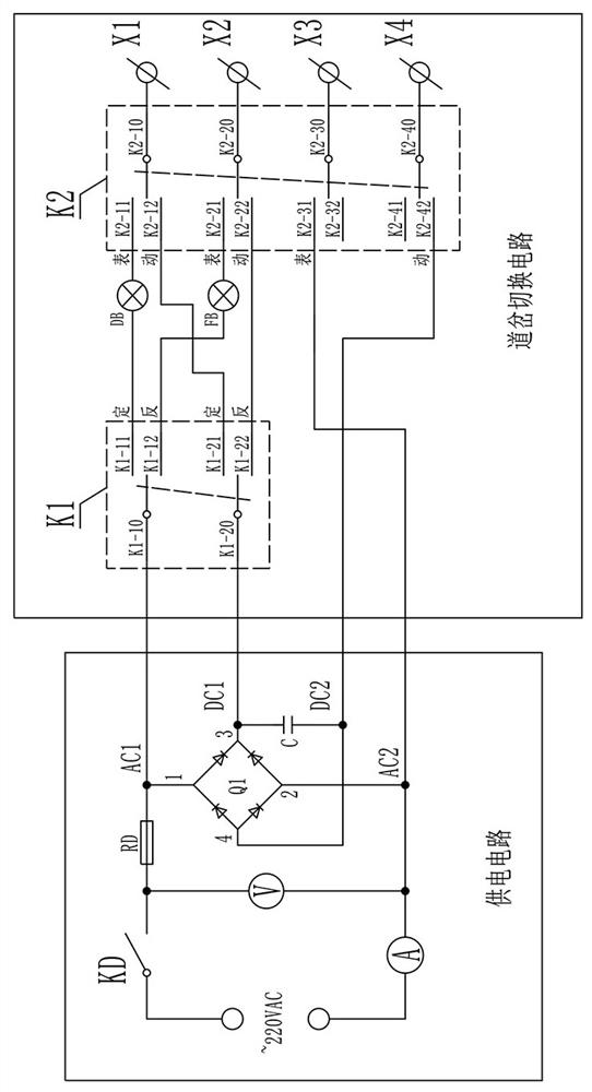
[0033] Embodiment one, see figure 1, the present invention is achieved through the following technical solutions: a portable turnout operating device, including a power supply circuit and a switch switching circuit, the power supply circuit includes an AC power interface and a rectifier bridge stack Q1 connected to the AC power interface, the rectifier bridge The two input terminals of stack Q1 are respectively AC1 and AC2, and the two output terminals are respectively DC1 and DC2; the switch switching circuit includes a double-pole double-throw switch K1, a position indicator light DB, a reverse position indicator light FB, and a four-pole double-throw switch K2, external terminals X1~X4, the switch combination of K1 and K2 corresponds to the connection relationship between external terminals X1~X4 and AC1, AC2, DC1, DC2 and the external power supply status of external terminals X1~X4; the external terminals X1~ X4 respectively correspond to the corresponding terminals on the...
Embodiment 2
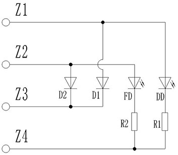
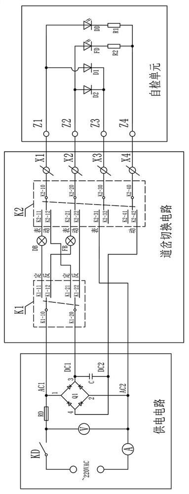
[0039] Embodiment 2, considering the reliability of debugging, it should be confirmed whether the function of the device is complete before debugging; if Figure 2-3 As shown, on the basis of Embodiment 1, a self-test unit is also included, and the self-test unit has terminals Z1-Z4 corresponding to the external terminals X1-X4 one-to-one, wherein a light-emitting diode DD is connected in series between Z1 and Z4 and current limiting resistor R1, a light emitting diode FD and a current limiting resistor R2 are connected in series between Z2 and Z4, a diode D1 is connected in series between Z1 and Z3, and a diode D2 is connected in series between Z2 and Z3. Wherein the positive end of D1 is connected to Z1, the positive end of D2 is connected to Z2, the positive end of light-emitting diode DD is connected to Z1, and the positive end of light-emitting diode FD is connected to Z2; before connecting to the switch machine, first use the self-inspection unit, Cooperate with the swit...
Embodiment 3
[0042] Embodiment three, such as Figure 1-Figure 4 As shown, a method for utilizing the portable switch operating device in Embodiment 2 to carry out switch operation includes the following steps:
[0043] S1. Initializing the device, setting K1 and K2 to zero, and connecting 220VAC to the AC power interface;
[0044] S2. Device self-inspection, connecting the terminals Z1~Z4 of the self-inspection unit to the external terminals X1~X4 in one-to-one correspondence; the self-inspection process is as follows:
[0045] S21, close the power switch KD, the voltmeter displays the power supply voltage, and the ammeter is 0;
[0046] S22. Toggle the K1 and K2, and sequentially set the combination of switches as positioning action, reverse action, positioning display, and reverse display, and corresponding LED DD, LED FD, positioning display lamp DB, and reverse display The light FB lights up separately in turn, indicating that the portable switch operating device is functioning norm...
PUM
 Abstract
Description
Claims
Application Information
 - Generate Ideas
- Intellectual Property
- Life Sciences
- Materials
- Tech Scout
- Unparalleled Data Quality
- Higher Quality Content
- 60% Fewer Hallucinations
Browse by: Latest US Patents, China's latest patents, Technical Efficacy Thesaurus, Application Domain, Technology Topic, Popular Technical Reports.
© 2025 PatSnap. All rights reserved.Legal|Privacy policy|Modern Slavery Act Transparency Statement|Sitemap|About US| Contact US: help@patsnap.com


