Wireless slide fence system and method

A fence, wireless technology, applied in the field of wireless sliding detection system, to achieve the effect of reducing risk, reducing risk and improving performance

Pending Publication Date: 2022-01-14
北伯林顿铁路公司
View PDF5 Cites 0 Cited by
  • Summary
  • Abstract
  • Description
  • Claims
  • Application Information

AI Technical Summary

Problems solved by technology

The present disclosure solves the technical problem of determining rock size and location to verify rock slip / fall alerts to reduce false alarms

Method used


Image

  • Wireless slide fence system and method
  • Wireless slide fence system and method
  • Wireless slide fence system and method

Examples


Embodiment Construction

[0016] A preferred version of the disclosure presented in the following written description and its various features and advantageous details will be more fully explained with reference to the non-limiting examples included in the drawings and as detailed in the ensuing description. Descriptions of well-known components are omitted so as not to unnecessarily obscure major features described herein. The examples used in the following description are intended to aid in the understanding of ways in which the present disclosure can be implemented and practiced. Therefore, these examples should not be construed as limiting the scope of the claims. Although the sliding barrier system may be described in terms of a particular wireless technology, any suitable signal transmission and reflection reception technology may be utilized. Accordingly, the disclosure herein is not intended to be limited to a particular wireless technology.

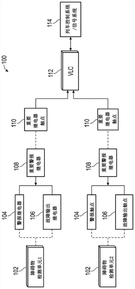
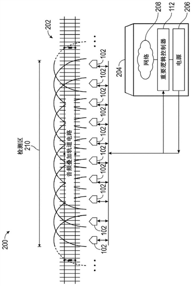
[0017] figure 1 A schematic diagram of a wireles...


PUM


Abstract

A Wireless Slide Fence utilizing signal reflection technology to detect rockslides and can determine the size and location of fallen rocks / objects impeding travel along a train track is presented. The present disclosure solves the technological problem of determining rock size and location to validate rockslide / fall alarms to reduce false alarms, while minimizing repairs required by conventional systems through the use of obstacle detection units and vital logic controllers. The present disclosure improves the performance of the system by, generating validated alarms when fallen rocks / objects satisfy the size criteria and are located in an area hazardous to train operations. In one exemplary embodiment, a loitering time can be implemented to validate object detections to reduce false positives due to transient objects such as migrating animals.

Description

technical field [0001] The present disclosure relates generally to object detection systems, and more particularly to wireless slip detection systems. Background technique [0002] It is common for debris and other objects to fall onto railroad tracks. These objects are obstacles that may affect the safe running of the train, resulting in derailment of the train or damage to the locomotive. The size of the object can greatly affect the extent of locomotive disruption. [0003] Traditional sliding barriers are installed at rockfall hazard locations to detect rockslides / falls that could impede travel along the track and cause damage to locomotives and / or injury to railroad personnel. A variety of sliding barrier types and configurations can be deployed to detect this potential hazard, but each has certain drawbacks. For example, an open line wire sliding fence includes line wire connected in series end-to-end for the length of the hazard zone. The power supply is connected...

Claims


Application Information

Patent Timeline
Patent Type & Authority Applications(China)
IPC IPC(8): B61L23/04
CPCB61L23/041B61L1/187G08B21/02G08B29/18G01S15/931G01S17/931G08B29/188G08B13/1609G08B13/181G08B21/18B61L15/0018G01S15/04B61L2205/00G01S17/04B61L29/30B61L27/53B61L27/70
Inventor M·比尔德P·C·施P·A·魏德勒J·W·史派西K·R·舒
Owner 北伯林顿铁路公司
Why Eureka
Try Eureka