
Nitrogen oxide control method in steam feeding initial combination stage of circulating fluidized bed boiler

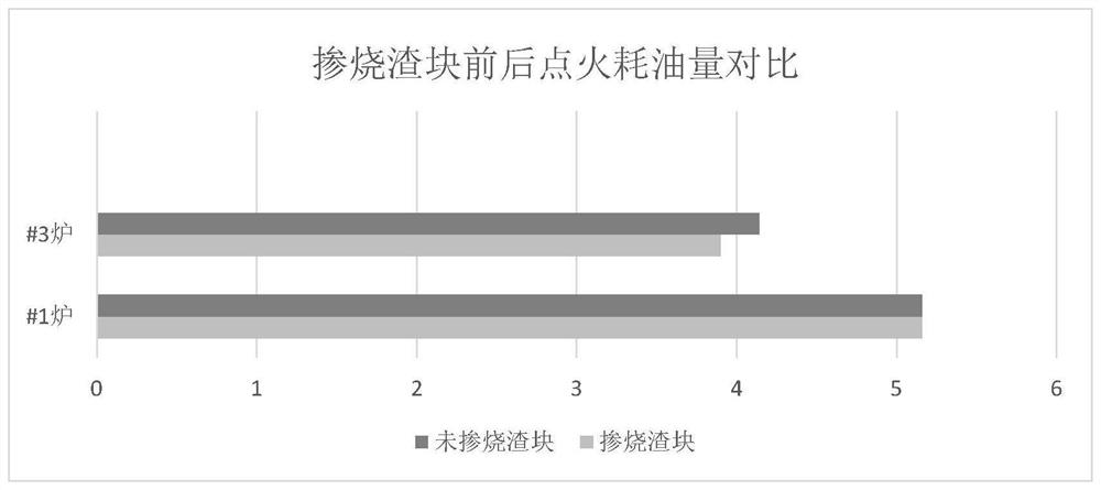
A circulating fluidized bed and nitrogen oxide technology, which is applied in fluidized bed combustion equipment, combustion methods, fuels burned in a molten state, etc., can solve the problem of controlling nitrogen oxide emissions, consuming more diesel, and affecting environmental protection electricity prices, etc. problems, to achieve the effect of reducing dosage, improving economic benefits and preventing dust accumulation

Pending Publication Date: 2022-01-11
华能苏州热电有限责任公司
View PDF0 Cites 0 Cited by
  • Summary
  • Abstract
  • Description
  • Claims
  • Application Information

AI Technical Summary

Problems solved by technology

However, within a few hours after the boiler is ignited and the furnace is fired, even if the amount of ammonia injection is adjusted to the maximum, the emission value of nitrogen oxides cannot be controlled at the ultra-clean emission value (≤50mg / Nm 3 ), which seriously affects the assessment of environmental protection electricity price
[0004] The existing technology also increases the thickness of the base material before ignition, so that the thickness of the material layer after the furnace is at a relatively high level, so that the temperature in the reaction zone rises to the optimum reaction temperature in a short period of time, but there are certain disadvantages in doing so. Disadvantages, that is, because the thickness of the material layer is already high before ignition, it will consume more diesel during the ignition process, and also because the thickness of the material layer is high, the fan speed needs to be increased to ensure that the fluidized bed boiler reaches a fluidized state , will increase the plant power consumption required in the ignition process, so although this method can effectively reduce the amount of ammonia water after the furnace is combined, it is not economical

Method used


Image

  • Nitrogen oxide control method in steam feeding initial combination stage of circulating fluidized bed boiler
  • Nitrogen oxide control method in steam feeding initial combination stage of circulating fluidized bed boiler
  • Nitrogen oxide control method in steam feeding initial combination stage of circulating fluidized bed boiler

Examples


Embodiment Construction

[0026] The implementation mode of the present invention is illustrated by specific specific examples below, and those who are familiar with this technology can easily understand other advantages and effects of the present invention from the contents disclosed in this description. Obviously, the described embodiments are a part of the present invention. , but not all examples. Based on the embodiments of the present invention, all other embodiments obtained by persons of ordinary skill in the art without making creative efforts belong to the protection scope of the present invention.

[0027] Below in conjunction with the examples, the specific implementation of the present invention will be further described in detail. The following examples are used to illustrate the present invention, but are not intended to limit the scope of the present invention.

[0028] A method for controlling initial nitrogen oxides of a circulating fluidized bed boiler combined furnace, wherein the ...


PUM


Abstract

The invention relates to the technical field of circulating fluidized bed production, in particular to a nitrogen oxide control method in a steam feeding initial combination stage of a circulating fluidized bed boiler. Fuel in a coal hopper before ignition of a fluidized bed boiler is a mixed material of coal and slag blocks, the emission value of nitrogen oxide can be controlled within 50mg / Nm<3> in the first hour after the boiler is ignited and being subjected to steam feeding, the NOX emission value is obviously controlled after optimization, the assessment requirement of the environmental protection electricity price can be completely met, the use amount of ammonia water is reduced, and the effects of preventing ash deposition of a tail flue air pre-heater and guaranteeing long-period and full-load safe and stable operation of the boiler are remarkable.

Description

technical field [0001] The invention relates to the technical field of circulating fluidized bed production, and more specifically, relates to a method for controlling nitrogen oxides at the initial stage of combining a circulating fluidized bed boiler. Background technique [0002] During the combustion process of circulating fluidized bed boilers, nitrogen oxides will be produced. In order to control the emission of nitrogen oxides in circulating fluidized bed boilers, in the prior art, ammonia gas is often injected into the tail of the furnace or cyclone separator to utilize Decomposition produces NH 2 The selective reduction reaction of the group, [0003] with NO and N 2 O reaction to reduce nitrogen oxide emissions. However, within a few hours after the boiler is ignited and the furnace is fired, even if the amount of ammonia injection is adjusted to the maximum, the emission value of nitrogen oxides cannot be controlled at the ultra-clean emission value (≤50mg / Nm ...

Claims


Application Information

Patent Timeline
Patent Type & Authority Applications(China)
IPC IPC(8): F23C10/28
CPCF23C10/28F23C2206/10
Inventor 蒋钧孙剑朱又红曹铮许国峰杨正戴峰徐伟陆冬冬杨晨
Owner 华能苏州热电有限责任公司
Learn More