
Grease distributor, grease lubricating system and lubricating grease changing system

A grease distributor and distributor technology, used in distribution devices, lubricating parts, engine lubrication, etc., can solve the problems of low oil replenishment accuracy and poor lubrication effect of lubricating parts, and achieve compact layout, easy processing, and simplified system. effect of structure

Pending Publication Date: 2022-01-11
AUTOL TECH
View PDF2 Cites 0 Cited by
  • Summary
  • Abstract
  • Description
  • Claims
  • Application Information

AI Technical Summary

Problems solved by technology

[0005] The purpose of the present invention is to provide a grease distributor, which is used to solve the technical problem of the current distributors that the oil replenishment accuracy of the oil storage chamber is low due to the reset of the spring to realize the oil replenishment of the oil storage chamber, and thus the lubrication effect of the lubricating part is poor;

Method used


Image

  • Grease distributor, grease lubricating system and lubricating grease changing system
  • Grease distributor, grease lubricating system and lubricating grease changing system
  • Grease distributor, grease lubricating system and lubricating grease changing system

Examples


specific Embodiment 1

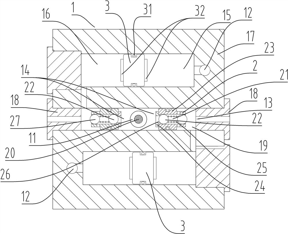
[0156] Specific embodiment 1 of the grease dispenser of the present invention: as figure 1 As shown, the grease distributor includes a distributor housing 1 and an oil distribution unit arranged on the distributor housing 1. In this embodiment, there are four oil distribution units. figure 1 Only two oil distribution units are shown in .

[0157] The distributor housing 1 has an oil supply channel 11 and an oil pressure channel 12. The oil supply channel 11 is used to supply grease to each oil distribution unit, and the oil pressure channel is used to supply fluid medium to each oil distribution unit. Each oil distribution unit shares the oil supply channel 11 , and each oil distribution unit shares the oil pressure channel 12 . The oil distribution unit includes an oil outlet 13, an oil supply chamber 14 communicated with the oil supply passage 11, and a power chamber 15 communicated with the pressure oil passage 12, and the oil outlet 13 is used for oil discharge. The oil ...

specific Embodiment 2

[0177] The specific embodiment 2 of the grease distributor of the present invention, the difference of the grease distributor in the above-mentioned specific embodiment 1 of the grease distributor in this embodiment is only: as image 3 As shown, the one-way valve core 222 in this embodiment is arranged on the housing 217, and an oil injection channel is additionally provided between the oil storage chamber 216 and the oil supply chamber 214, and the one-way valve core 222 is arranged in the oil injection channel. The function of the oil supply valve core 202 in the embodiment is to control the opening and closing of the oil outlet 213 . In order to ensure that the oil supply spool 202 is stably in the oil storage state, a spool rod is provided on the side of the oil supply spool 202 close to the oil storage chamber 216, and the spool rod extends into the housing 217 and fits in a sliding seal with the housing 217, The pressure receiving area of ​​the oil supply valve core 202...

specific Embodiment 3

[0179] The specific embodiment 3 of the grease distributor of the present invention, the difference of the grease distributor in the above-mentioned specific embodiment 1 of the grease distributor in this embodiment is only: as Figure 4 As shown, in this embodiment, the oil supply valve core is an elastic valve core integrally formed, and an elastic cup 3021 is arranged on the outer periphery of the elastic valve core, and the mouth of the elastic cup 3021 is set facing away from the oil supply chamber 314. 3021 constitutes the one-way oil passing structure. In this embodiment, the oil outlet 313 is arranged on the cover 318 of the oil supply valve core, and one end surface of the oil supply valve core 302 in the moving direction forms a sealing surface of the oil outlet 313 for sealing the oil outlet 313 . The moving direction of the oil pressure piston 3 in this embodiment is consistent with the moving direction of the oil supply valve core 302 .


PUM


Abstract

The invention relates to a grease distributor, a grease lubricating system and a lubricating grease changing system. The grease distributor comprises a distributor shell, wherein grease distribution units are arranged on the distributor shell; when grease storage cavities store grease, a grease supply channel supplies the grease to grease supply cavities to enable grease supply valve elements to plug grease outlets, the grease enters the grease storage cavities through a one-way grease passing structure, and grease pressing pistons extrude power cavities to reduce the size of the power cavities; and when the grease is discharged from the grease storage cavities, the grease pressing channel supplies fluid media to the power cavities to enable the grease supply valve elements to open the grease outlets, and the grease pressing pistons extrude the grease in the grease storage cavities to be discharged from the grease outlets. Due to the fact that the grease storage cavities do not depend on a spring to apply pressure in the process of injecting the grease outwards, the problem that the grease cannot be accurately supplemented due to fatigue of the spring can be avoided, meanwhile, the grease injection pressure in the process of injecting the grease into the grease storage cavities is small, and the technical problem that according to an existing distributor, grease supplementing of an grease storage cavity is achieved through reset of a spring, accordingly, the grease supplementing precision is low, and the lubricating quality of a lubricating part is poor is solved.

Description

technical field [0001] The invention relates to a grease distributor, a grease lubricating system and a lubricating grease changing system. Background technique [0002] At present, some industrial machinery and equipment need to carry out centralized lubrication on each lubrication point on the machine, and the centralized lubrication is carried out in a regular and quantitative manner through the lubrication equipment. At the same time, in order to ensure the better lubricating effect of the lubricating grease, it needs to be replaced regularly, but when adding new lubricating grease to the lubricating point, it is necessary to discharge the old grease. [0003] The Chinese patent application with the application publication number CN110848549A and the application publication date of 2020.02.28 discloses a lubrication system, including at least one dual oil circuit control suction and discharge device, the oil pump module controls the dual oil circuit control grease suctio...

Claims


Application Information

Patent Timeline
Patent Type & Authority Applications(China)
IPC IPC(8): F16N25/00F16N25/02F16N23/00F16N7/38F16N31/00
CPCF16N25/00F16N25/02F16N23/00F16N7/38F16N31/00
Inventor 赵民章司艳凯刘新功王利超
Owner AUTOL TECH
Learn More