
Manipulator motion path simulation method

A simulation method and motion path technology, applied in the field of manipulators, can solve problems such as workpiece damage and processing parts collision, and achieve the effects of ensuring integrity, ensuring safety, and avoiding damage

Active Publication Date: 2022-01-11
浙江精尚数控科技有限公司
View PDF4 Cites 0 Cited by
  • Summary
  • Abstract
  • Description
  • Claims
  • Application Information

AI Technical Summary

Problems solved by technology

[0003] When the manipulator is in operation, it needs to grab the workpiece so that the workpiece can be moved to the processing position. During the movement of the manipulator to grab the workpiece, the manipulator may collide with the processing part without determining the moving path, resulting in The workpiece is damaged, and when the workpiece is grasped, if the manipulator does not choose a suitable contact position with the workpiece, it is easy to cause the workpiece to be damaged

Method used


Image

  • Manipulator motion path simulation method
  • Manipulator motion path simulation method
  • Manipulator motion path simulation method

Examples


Embodiment Construction

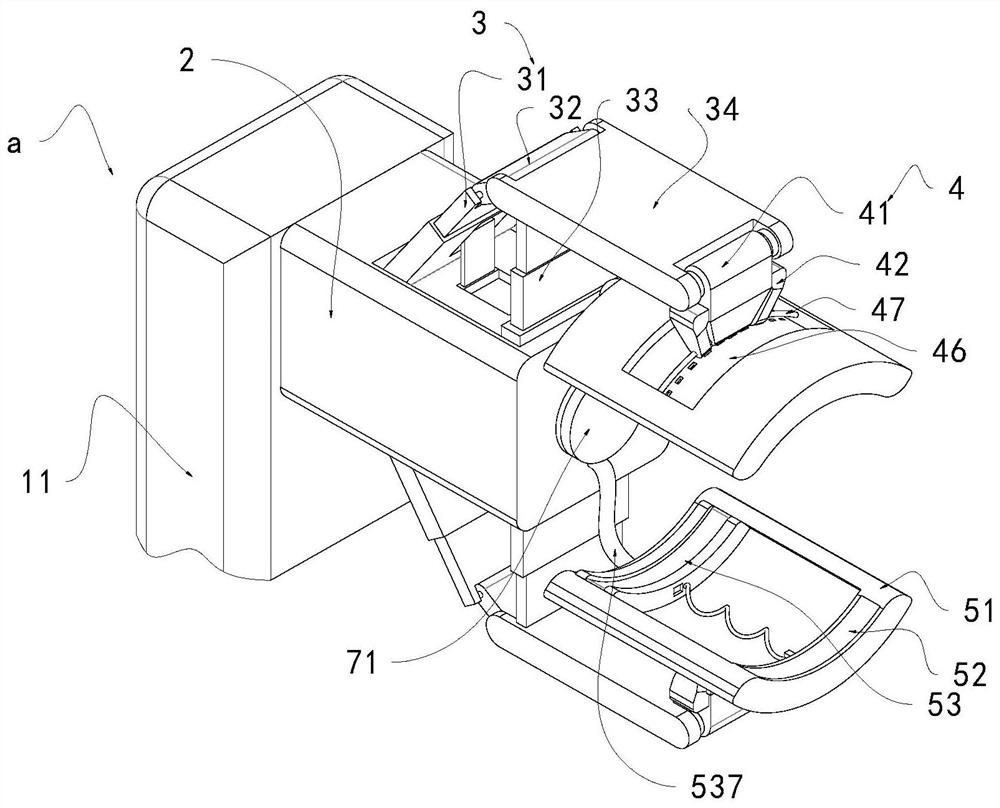
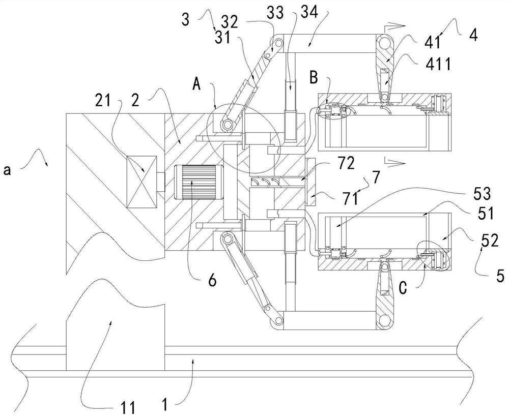
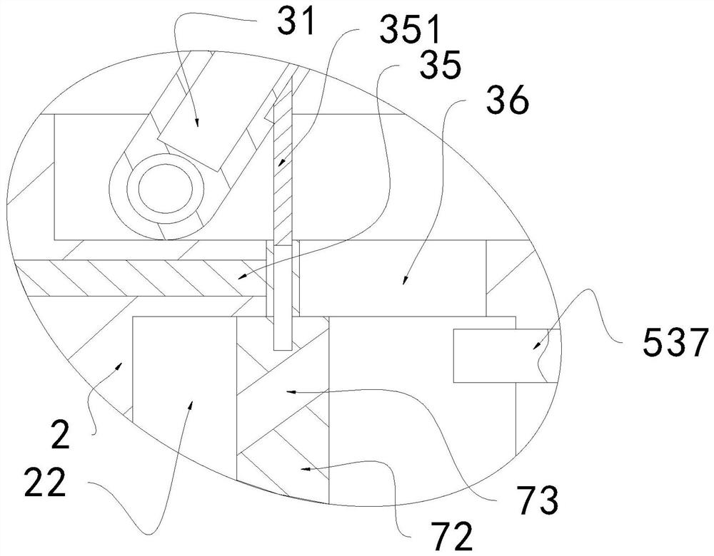
[0034] see Figure 1-8 A method for simulating the motion path of a manipulator, the steps are as follows:

[0035] The first step is to move the manipulator a to the position of the double-spindle machining center, and lay the working track 1 on the moving path of the manipulator a, so that the central control system can establish the coordinate system of the workpiece position and the coordinate system of the manipulator a in the same coordinate system Next, to determine the specific spatial position of the manipulator a in the coordinate system;

[0036] The second step is to obtain the initial mathematical model of the unprocessed workpiece surface, denoted as b1, and at the same time retrieve the programmed workpiece surface shape on the dual-spindle machining center, and perform mathematical modeling on it, denoted as the programmed workpiece surface mathematical model b2 , through b2 to determine the specific position coordinates of the workpiece after machining in the...


PUM


Abstract

The invention discloses a manipulator motion path simulation method, and belongs to the field of manipulators. The manipulator motion path simulation method comprises the following steps that 1, a manipulator is moved to the position of a double-spindle machining center, a working track is laid on a moving path of the manipulator, and a workpiece position coordinate system and a coordinate system of the manipulator are established in one same coordinate system through a central control system, so that a specific spatial position of the manipulator in the coordinate system is determined; space coordinates of the manipulator and the working track and workpiece position coordinates are established in the same coordinate system, and a workpiece prototype and a modeled surface mathematical model are connected with the coordinate system, so that a preliminary path image suitable for the manipulator to pick and place a workpiece is formed, and a final path image is determined through trial operation of the manipulator; and in the trial operation process, the maximum extension distance of the manipulator is kept, so that the integrity and the safety of the motion path of the manipulator are guaranteed.

Description

technical field [0001] The invention relates to the field of manipulators, and more specifically, relates to a method for simulating a movement path of a manipulator. Background technique [0002] With the rapid development of automation technology, manipulators are usually used in industrial production to reduce labor costs and improve production efficiency. The manipulator is an automatic operating device that can imitate the movement of the human arm, grab and carry objects or operate tools according to a fixed program. It can move freely in three dimensions, so that it can operate objects or tools located at different stations. [0003] When the manipulator is in operation, it needs to grab the workpiece so that the workpiece can be moved to the processing position. During the movement of the manipulator to grab the workpiece, the manipulator may collide with the processing part without determining the moving path, resulting in The workpiece is damaged, and when the wor...

Claims


Application Information

Patent Timeline
Patent Type & Authority Applications(China)
IPC IPC(8): B25J9/16B25J15/08B23Q7/04
CPCB25J9/16B25J9/1664B25J9/1666B25J9/1694B23Q7/04B25J15/08
Inventor 余良斌
Owner 浙江精尚数控科技有限公司
Learn More