A kind of bias control loop of pa chip

A technology of bias control and control circuit, applied in control/regulation systems, instruments, regulating electrical variables, etc., can solve problems such as increasing circuit cost, reducing control accuracy, voltage or current error and loss, and reducing current loss , The effect of reducing circuit cost and improving accuracy

Active Publication Date: 2022-03-18
深圳市时代速信科技有限公司
View PDF8 Cites 0 Cited by
  • Summary
  • Abstract
  • Description
  • Claims
  • Application Information

AI Technical Summary

Problems solved by technology

[0004] However, the above-mentioned control circuit has the following technical problems: the method of forming feedback through the collector and the base, generally samples the collector current of the sensor, and feeds back an appropriate voltage to the triode to drive the base of the triode, sometimes in order to improve the characteristics of the PA , it is also necessary to add a suitable current compensation waveform, which makes the circuit very complicated, and it is difficult to directly obtain the integrated current waveform in the integrated circuit. It is necessary to obtain the integrated voltage waveform first, and then convert the integrated voltage waveform into the integrated current waveform. In order to obtain For the final control voltage, it is necessary to first integrate the current to generate an integral voltage, then convert the integral voltage into an integral current, perform calculations with the sampled current, and finally convert it into a control voltage
Such frequent conversion of voltage and current requires an additional conversion circuit, which makes the circuit very complicated and increases the cost of the circuit. In addition, errors and losses may occur in the voltage or current during the conversion process, and it is easy to reduce the control accuracy.

Method used


Image

  • A kind of bias control loop of pa chip
  • A kind of bias control loop of pa chip
  • A kind of bias control loop of pa chip

Examples


Embodiment Construction

[0038] The technical solutions in the embodiments of the present invention will be clearly and completely described below with reference to the accompanying drawings in the embodiments of the present invention. Obviously, the described embodiments are only a part of the embodiments of the present invention, but not all of the embodiments. Based on the embodiments of the present invention, all other embodiments obtained by those of ordinary skill in the art without creative efforts shall fall within the protection scope of the present invention.

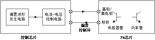
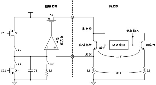
[0039] The control circuit has the following technical problems: the feedback method is formed by the collector and the base. Generally, the collector current of the sensor is sampled, and the appropriate voltage is fed back to the triode to drive the base of the triode. Sometimes, in order to cover the characteristics of the PA, It is also necessary to add a suitable current compensation waveform, which makes the circuit very complica...


PUM


Abstract

The invention discloses a bias control loop of a PA chip. The bias control loop includes: a control chip and a PA chip; the control chip is provided with a bias waveform generation circuit and a current and voltage control circuit connected to each other. The PA chip is provided with a sensor tube, the base terminal of the sensor tube is connected to the collector terminal; the current and voltage control circuit is respectively connected to the emitter terminal of the sensor tube and the base terminal and the collector terminal of the sensor tube Connection end connection. The invention can collect the emitter voltage of the sensor tube on the PA chip, and perform calculation on the voltage correction waveform and feedback waveform, and finally convert it into a bias current and directly transmit it to the collector and base of the sensor tube, forming a simple closed loop The control circuit is used to simplify the structure of the control circuit and reduce the cost of the circuit, and only one voltage and current conversion is required in the entire control process, which can reduce the current loss caused by the conversion, thereby improving the control accuracy.

Description

technical field [0001] The invention relates to the technical field of control circuits, in particular to a bias control loop of a PA chip. Background technique [0002] With the development of WIFI technology, its throughput continues to increase, and in the FEM of WIFI, GaAs technology is generally used to achieve power amplification to achieve sufficient linearity and output power. But the output power of GaAs power amplifier is related to parameters such as the current gain of the power amplifier, and these parameters are related to temperature. In order to make the output power of the power amplifier fast and stable, it is generally necessary to control the current of the power amplifier. [0003] In order to accurately control the bias current of the power amplifier from power-on to stabilization, the commonly used control method is to use a closed-loop control circuit. The circuit principle is to use a small-sized triode as a temperature sensor, which is placed in th...

Claims


Application Information

Patent Timeline
Patent Type & Authority Patents(China)
IPC IPC(8): G05F1/56
CPCG05F1/56
Inventor 张孟文
Owner 深圳市时代速信科技有限公司
Why Eureka
Try Eureka