Bi-frequency metal locator

A metal detector, frequency technology, applied in the field of metal detectors, can solve problems such as increasing the complexity of detectors

Inactive Publication Date: 2004-02-18
NO 27 ELECTRONICS INST MINIST OF INFORMATION IND +1
View PDF1 Cites 0 Cited by
  • Summary
  • Abstract
  • Description
  • Claims
  • Application Information

AI Technical Summary

Problems solved by technology

[0029] Controlling the appropriate phase can effectively suppress the interference of weakly conductive and magnetic background signals such as seawater and magnetic soil, but this detector needs to be equipped with two independent phase control rectifiers, which increases the complexity of the detector design

Method used


Image

  • Bi-frequency metal locator
  • Bi-frequency metal locator
  • Bi-frequency metal locator

Examples


Embodiment Construction

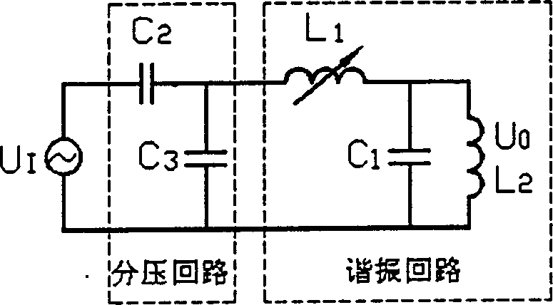
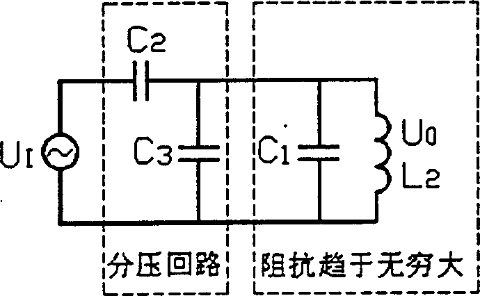
[0058] With the help of Figure 2(a) ~ 2(c) The implementation and frequency selection of the dual-frequency transmitting circuit of the dual-frequency metal detector according to the present invention are described.

[0059] As shown in Figure 2(a), the dual-frequency transmitting circuit consists of a resonant circuit (a two-terminal network with double resonant points) and a voltage divider circuit, where L 2 is the transmitting coil, U O For the output transmit signal, U I For the input transmit signal, L 1 is the adjustable inductance, C 1 is the resonant capacitor, C 2 、C 3 For the AC voltage divider capacitor.

[0060] The resonance tank impedance is: Z = jωL 1 + jω L 2 ( - j 1 ω ...


PUM


Abstract

A metal locator for locating the underground object containing less metal by low-frequency electromagnetic induction principle features that the bi-frequency non-resonance receiving technique and phase-shifting technique are used in time-division mode to detect the resistor and reactance components in received signals, so effectively suppressing the eddy effect of weakly electric background and the magnetic effect of weekly magnetic background. The bi-frequency constant-amplitude superposition mode and full-wave phase-sensitive rectifying technique are used for high sensitivity to different metal objects.

Description

technical field [0001] The invention relates to a metal detector for detecting underground targets containing a small amount of metal, in particular to using the principle of low-frequency electromagnetic induction, adopting dual-frequency superposition continuous working mode and full-wave phase-sensitive detection technology to detect ferromagnetic metal targets and non-ferromagnetic metal targets in All metal targets within. Background technique [0002] The working principle of the dual-frequency metal detector is briefly described below. [0003] Dual-frequency metal detectors are used to detect underground targets containing a small amount of metal, overcoming the shortcomings of single-frequency metal detectors that are difficult to use in seawater, magnetic soil and other conductive and magnetic background environments. Due to the dual-frequency superposition continuous working mode and full-wave phase-sensitive detection technology, the dual-frequency metal detecto...

Claims


Application Information

Patent Timeline
Patent Type & Authority Patents(China)
IPC IPC(8): G01V3/11
Inventor 庞瑞帆钟翔胡泷何云龙徐毅刚房旭民
Owner NO 27 ELECTRONICS INST MINIST OF INFORMATION IND
Why Eureka
Try Eureka