


Quick Research
Generate reliable direction feasibility study reports for your R&D in just a few steps.

Technical Q&A
Discover and master advanced knowledge NOW. Basics, ideas, possibilities, all at once.

Find Solutions
As an expert in R&D theories, this can generate solutions to your technical problems instantly.

Evaluate Feasibility
Analyze your overall solution with one click, know your potential R&D risks in advance.

Monitor Landscape
Get weekly tech updates, stay abreast of the latest tech innovations and key insights.
Laser welding system and welding method thereof
A laser welding and butt end technology, applied in laser welding equipment, welding equipment, metal processing equipment, etc., can solve the problem of not being suitable for welding of automobile shock absorbers, and achieve the effect of facilitating welding and improving work efficiency
- Summary
- Abstract
- Description
- Claims
- Application Information
AI Technical Summary
Problems solved by technology
Method used
Image

Examples
Embodiment 1
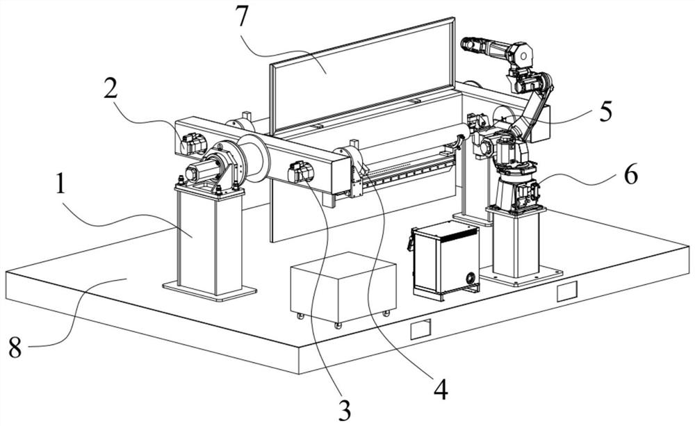
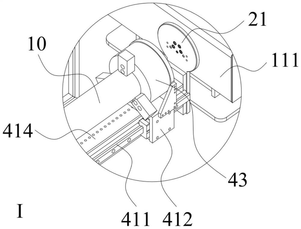
[0044] like Figure 1 to Figure 11 Shown is the first embodiment of a laser welding system of the present invention, including a control device, a displacement device and a six-axis laser welding device 6 communicated with the control device; the displacement device includes a turning frame device 1 and a The first rotating mechanism 2 and the second rotating mechanism 3 on the flip rack device 1. The first rotating mechanism 2 includes a first rotating butt end and a second rotating butt end, and the second rotating mechanism 3 includes a third rotating butt The rotating butt end, the first rotating butt end and the third rotating butt end are provided with an adjustable clamping mechanism 4, the second rotating butt end and the fourth rotating butt end are both provided with a clamping and abutting mechanism 5; , The first rotating mechanism 2, the second rotating mechanism 3, the adjustable clamping mechanism 4, and the clamping abutting mechanism 5 are all connected with t...
Embodiment 2
[0055] This embodiment is similar to Embodiment 1, except that in this embodiment, the main frame 11 is further provided with a shielding structure 7 for shielding the radiation emitted by the six-axis laser welding device 6 . like figure 1 and figure 2 As shown, the shielding structure 7 is a shielding plate, and the shielding plate is connected with the main frame 11 .
Embodiment 3
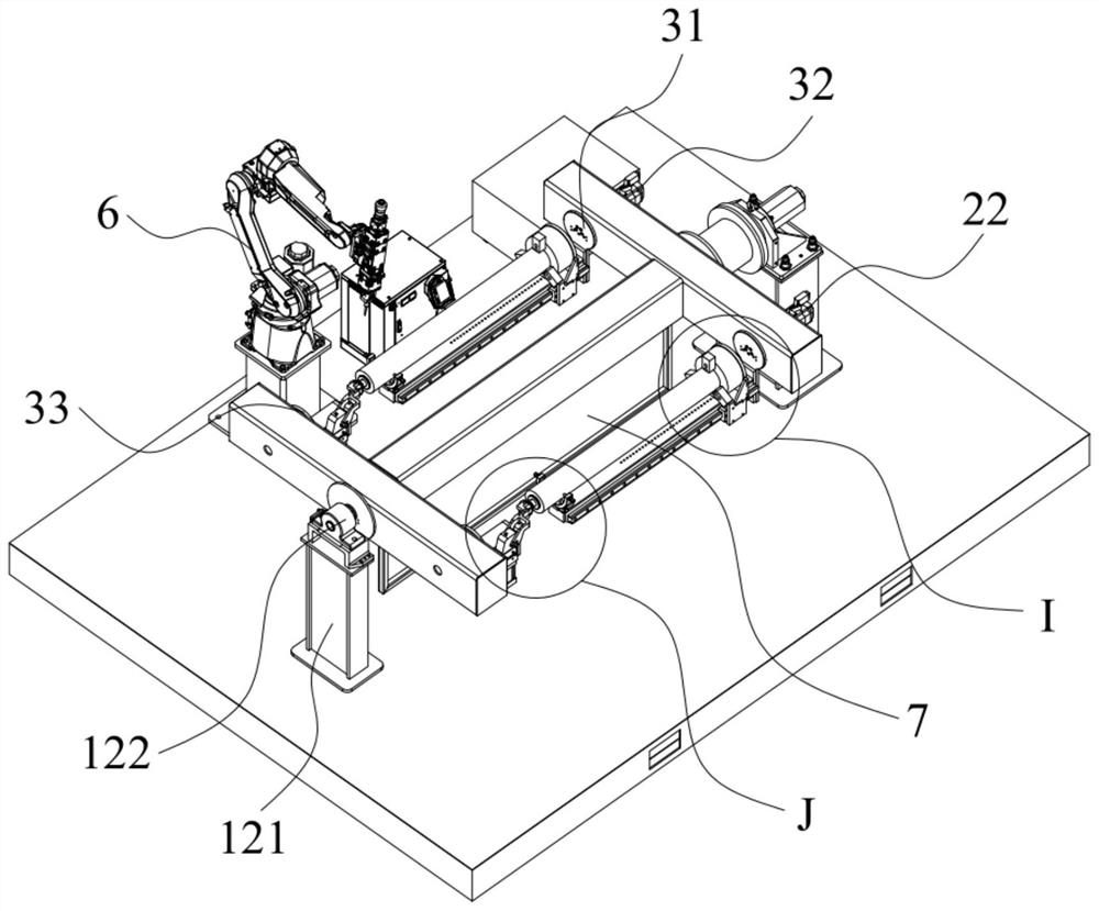
[0057] like image 3 and Figure 9 As shown, this embodiment is similar to Embodiment 1 or 2, the difference is that in this embodiment, the main frame 11 includes a first support rod 111, a second support rod 112, and the first support rod 111 and the second support rod 112 are parallel to each other, and the first support rod 111 and the second support rod 112 are connected by a connecting rod 113; the shielding plate is connected to the upper or lower surface of the connecting rod 113 along the extending direction of the connecting rod The upper surface and the lower surface of the connecting rod 113; the turning mechanism 13 and the follower mechanism 12 are respectively connected with the outer sides of the first support rod 111 and the second support rod 112; the first drive plate 21 and the second drive plate 31 are connected to the first The inner side of the support rod 111 is connected, and both the first follower plate 23 and the second follower disk 33 are connect...
PUM
 Abstract
Description
Claims
Application Information
 - R&D Engineer
- R&D Manager
- IP Professional
- Industry Leading Data Capabilities
- Powerful AI technology
- Patent DNA Extraction
Browse by: Latest US Patents, China's latest patents, Technical Efficacy Thesaurus, Application Domain, Technology Topic, Popular Technical Reports.
© 2024 PatSnap. All rights reserved.Legal|Privacy policy|Modern Slavery Act Transparency Statement|Sitemap|About US| Contact US: help@patsnap.com