Liquid separation and purification device

A technology of liquid separation and separation barrel, which is applied in the direction of separation method, sedimentation separation, feeding/discharging device of settling tank, etc. It can solve the problems of easy wear of filter screen, long settling time of container, waste of time, etc., and achieve high purity , Reduce the effect of impurity suspended state

Inactive Publication Date: 2022-01-07
唐青松
View PDF0 Cites 0 Cited by
  • Summary
  • Abstract
  • Description
  • Claims
  • Application Information

AI Technical Summary

Problems solved by technology

[0002] At present, natural precipitation or mechanical filtration are mostly used for liquid separation and purification. Both of the above two methods have their own disadvantages. First, natural precipitation requires a huge container and a long settling time, so it is extremely time-consuming. Second, mechanical filtration Mechanical equipment is required, and the filter screen needs to be replaced and cleaned frequently, which is extremely time-consuming, and the filter screen is easy to wear during the cleaning process. Therefore, when the liquid passes through the filter screen, it is blocked by the filter screen and the flow rate is slowed down. The above two methods are not applicable. Liquid with a fast flow rate, so a liquid separation and purification device is required

Method used


Image

  • Liquid separation and purification device
  • Liquid separation and purification device
  • Liquid separation and purification device

Examples


Embodiment Construction

[0026] The following will clearly and completely describe the technical solutions in the embodiments of the present invention with reference to the accompanying drawings in the embodiments of the present invention. Obviously, the described embodiments are only some, not all, embodiments of the present invention. Based on the embodiments of the present invention, all other embodiments obtained by persons of ordinary skill in the art without making creative efforts belong to the protection scope of the present invention.

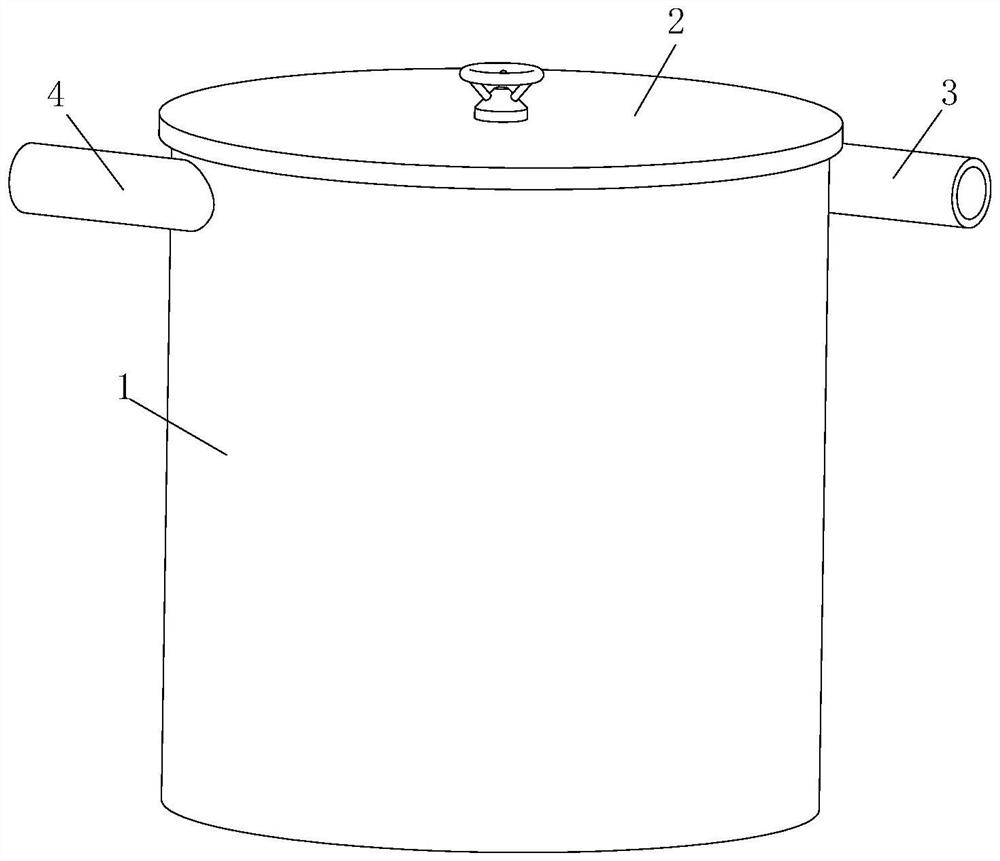
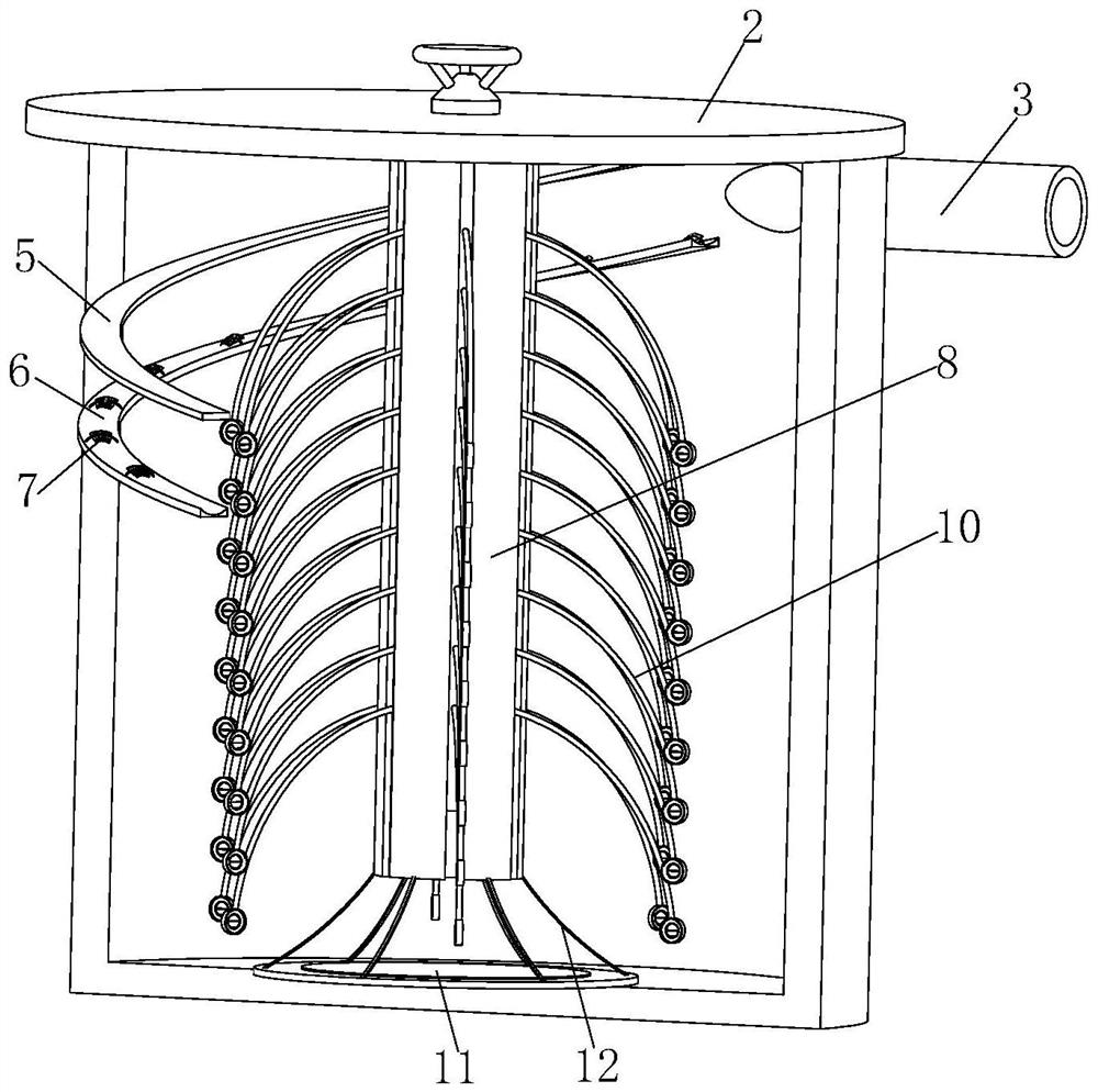
[0027] see Figure 1-7 , the present invention provides a technical solution: a liquid separation and purification device, comprising a separation barrel 1, an upper cover 2, a liquid inlet 3 and a liquid outlet 4, the upper cover 2 is located on the upper end of the separation barrel 1, and the liquid outlet 4 and the liquid inlet 3 are respectively fixedly installed on the left and right sides of the separation barrel 1 near the upper end, the inner wall of ...


PUM


Abstract

The invention relates to the technical field of liquid separation and purification, and discloses a liquid separation and purification device, which comprises a separation barrel, an upper cover, a liquid inlet and a liquid outlet, wherein the upper cover covers the upper end of the separation barrel, the liquid outlet and the liquid inlet are fixedly formed in the left side and the right side, close to the upper end, of the separation barrel correspondingly, a first guide plate and a second guide plate are fixedly mounted on the inner wall of the separation barrel, an auxiliary mechanism is mounted on the upper wall of the second guide plate, a fixing sleeve is fixedly mounted at the lower end of the upper cover, a rotating shaft is sleeved with the fixing sleeve, the upper end of the rotating shaft penetrates through the upper cover, and a rubber rod is fixedly mounted on the outer wall of the rotating shaft. According to the invention, a liquid anticlockwise flows from top to bottom, so that the rotating effect is achieved, the purpose of concentrating impurities is achieved, purification can be achieved under the condition that the flow speed is high, and the flowing-out liquid is higher in purity; and a rubber rod is in a swinging state, so that suspended impurities can be more easily attached to fluff, and the liquid is further purified.

Description

technical field [0001] The invention relates to the technical field of liquid separation and purification, in particular to a liquid separation and purification device. Background technique [0002] At present, natural precipitation or mechanical filtration are mostly used for liquid separation and purification. Both of the above two methods have their own disadvantages. First, natural precipitation requires a huge container and a long settling time, so it is extremely time-consuming. Second, mechanical filtration Mechanical equipment is required, and the filter screen needs to be replaced and cleaned frequently, which is extremely time-consuming, and the filter screen is easy to wear during the cleaning process. Therefore, when the liquid passes through the filter screen, it is blocked by the filter screen and the flow rate is slowed down. The above two methods are not applicable. Liquid with a faster flow rate, so a liquid separation and purification device is required. ...

Claims


Application Information

Patent Timeline
IPC IPC(8): B01D21/02B01D21/00B01D21/24
CPCB01D21/02B01D21/0087B01D21/245
Inventor 唐青松
Owner 唐青松
Why Eureka
Try Eureka