
Omnidirectional matching non-uniform energy receiving surface for line source radiation

An energy-receiving, non-uniform technology, applied in the radiating element structure, antenna-grounding switch structure connection, antenna and other directions, can solve the problems of unsatisfactory receiver performance, reduced receiving efficiency of receiving metasurface, and deterioration of impedance mismatch, etc. Excellent performance, light weight and improved absorption efficiency

Active Publication Date: 2022-01-04
ZHEJIANG UNIV
View PDF8 Cites 0 Cited by
  • Summary
  • Abstract
  • Description
  • Claims
  • Application Information

AI Technical Summary

Problems solved by technology

However, the above-mentioned uniform energy-receiving metasurface is usually only suitable for specific plane wave incidence such as normal incidence.
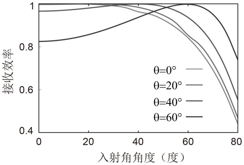
As the incident angle of microwave energy increases, the impedance mismatch deteriorates rapidly, and the receiving efficiency of the corresponding receiving metasurface will also decrease rapidly
As a result, their performance as receivers is generally not ideal when the radiant energy is incident as a non-plane wave, such as from a line source

Method used


Image

  • Omnidirectional matching non-uniform energy receiving surface for line source radiation
  • Omnidirectional matching non-uniform energy receiving surface for line source radiation
  • Omnidirectional matching non-uniform energy receiving surface for line source radiation

Examples


Embodiment Construction

[0034] The present invention will be further described below in conjunction with the accompanying drawings and embodiments.

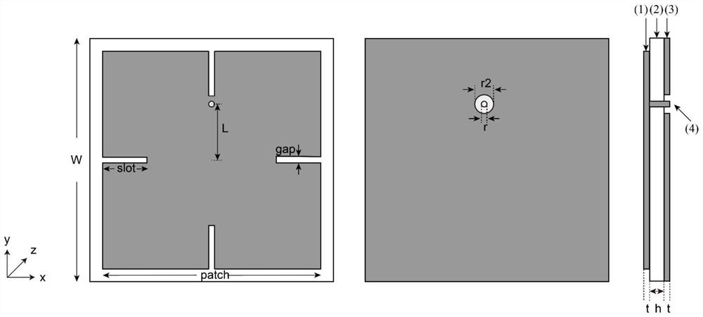
[0035] like figure 1 As shown, the non-uniform surface is mainly composed of square sub-wavelength resonant units whose unit size is less than 1 / 4 of the working wavelength, which can be regarded as a uniform medium. Each sub-wavelength resonant unit is mainly composed of the first metal copper sheet 1, The first dielectric layer 2 and the second metal copper sheet 3 are composed of the first metal copper sheet 1 and the second metal copper sheet 3 in the shape of square sheets, the first metal copper sheet 1 and the second metal copper sheet 3 have the same thickness, and the first metal copper sheet 1 and the second metal copper sheet 3 have the same thickness. The side length of the metal copper sheet 1 is less than the side length of the second metal copper sheet 3, the first dielectric layer 2 is a square block, the thickness of the first dielectri...


PUM

PropertyMeasurementUnit
thicknessaaaaaaaaaa
thicknessaaaaaaaaaa

Abstract

The invention discloses an omnidirectional matching non-uniform energy receiving surface for line source radiation. The omnidirectional matching non-uniform energy receiving surface is formed by arranging a plurality of square sub-wavelength resonance units; four sides of a first metal copper sheet are provided with four identical strip-shaped gaps from the midpoints of the corresponding sides in the radial direction respectively; the first metal copper sheet is provided with a via hole; the via hole is formed in a radial straight line between one strip-shaped gap of the first metal copper sheet and the center of the first metal copper sheet, penetrates through a first dielectric layer and is electrically connected with the first metal copper sheet; a through hole is coaxially formed in a second metal copper sheet at the via hole; the radius of the through hole is larger than that of the via hole; and the via hole is electrically connected with the second metal copper sheet. The omnidirectional matching non-uniform energy receiving surface is simple in structure, small in size and light in weight, can be designed into different shapes and sizes, is regarded as a uniform medium, has an excellent energy receiving effect on incident waves at various angles, does not need to damage raw materials during use, and can be widely applied to military and civil fields such as wireless energy transmission, antennas, communication systems, electromagnetic shielding and the like.

Description

technical field [0001] The invention relates to a non-uniform artificial electromagnetic surface, which belongs to the field of wireless microwave energy reception, and specifically relates to a non-uniform sub-wavelength resonance unit regularly arranged to realize omnidirectional matching energy reception for radiation at various angles of a line source at a specific distance non-uniform surface. Background technique [0002] Microwave wireless power transmission (MWPT) has always been a hot topic in electrical and microwave studies because of its wide application prospects in wireless charging and space solar satellite systems. In MWPT systems, a key factor is reception efficiency, which is directly determined by the reception antenna used to receive wireless energy. Conventional receive antennas or antenna arrays have some inherent limitations, such as unavoidable backscatter, suboptimal aperture efficiency, and unavoidable impedance mismatch, which will cause reflectio...

Claims


Application Information

Patent Timeline
Patent Type & Authority Applications(China)
IPC IPC(8): H01Q1/38H01Q1/50H01Q23/00
CPCH01Q1/38H01Q1/50H01Q23/00
Inventor 汤婧鑫叶德信
Owner ZHEJIANG UNIV
Learn More