
Circuit breaker energy storage indication interlocking mechanism

A technology of interlocking mechanism and circuit breaker, applied in contact operating mechanism, switchgear status indication, protection switch operation/release mechanism, etc. problems, to achieve the effect of extending the service life, improving the replaceability, and reducing the difficulty of maintenance

Pending Publication Date: 2022-01-04
SHANGHAI LIANGXIN ELECTRICAL
View PDF1 Cites 0 Cited by
  • Summary
  • Abstract
  • Description
  • Claims
  • Application Information

AI Technical Summary

Problems solved by technology

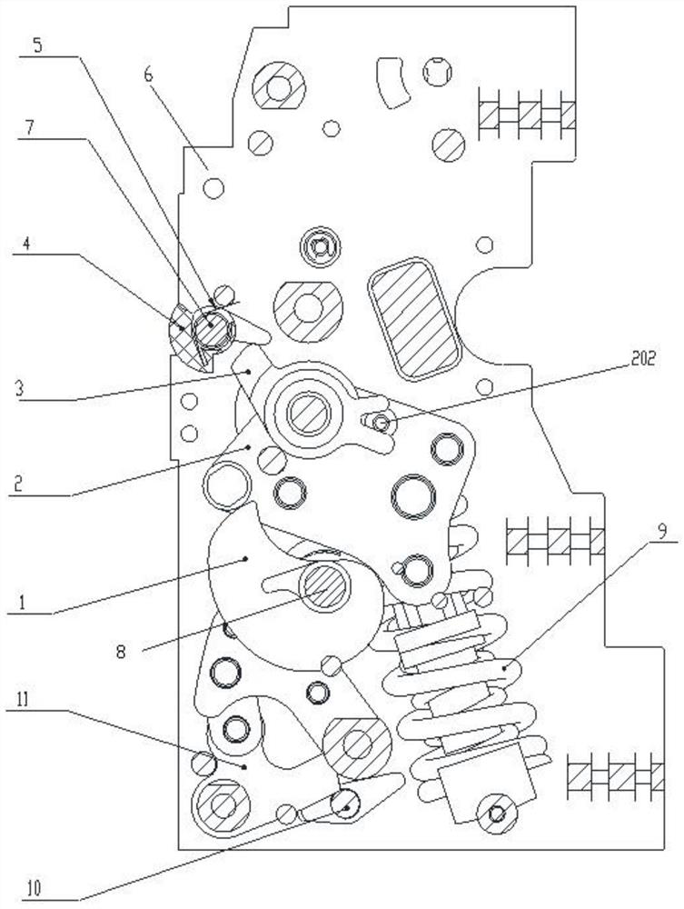
[0005] The purpose of the present invention is to provide a circuit breaker energy storage indicator for the technical defects of the above-mentioned existing circuit breaker operating mechanism energy storage indicator device, such as poor replaceability, complicated maintenance and easy damage to the switching state of the indicator when the energy is released at a high speed. The interlock mechanism transmits energy storage information through the lever installed coaxially on the energy storage lever, avoiding the direct linkage between the energy storage lever and the energy storage indicator, improving the interchangeability of the circuit breaker energy storage indicator interlocking mechanism, and reducing the It is difficult to maintain, and at the same time, the slow speed of energy storage has a small impact on the energy storage indicator. When the energy is released, the lever rotates counterclockwise, and the energy storage indicator automatically resets under the action of the energy storage reset part to switch the indication state. Small, the whole structure prolongs the service life of the energy storage indicator

Method used


Image

  • Circuit breaker energy storage indication interlocking mechanism
  • Circuit breaker energy storage indication interlocking mechanism
  • Circuit breaker energy storage indication interlocking mechanism

Examples


Embodiment 1

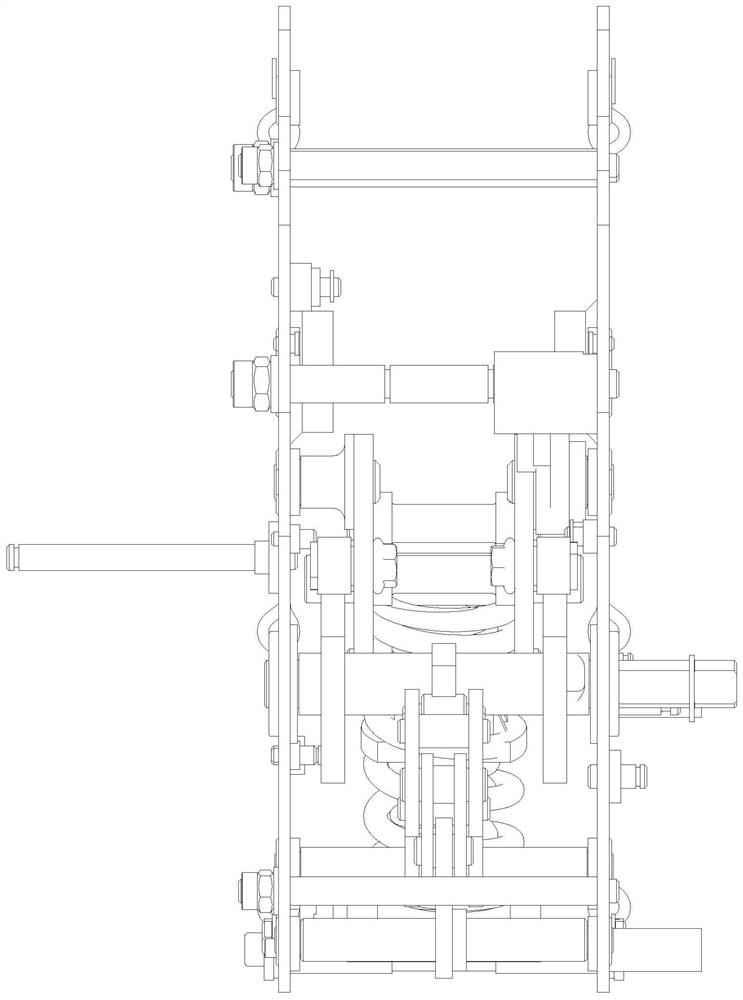
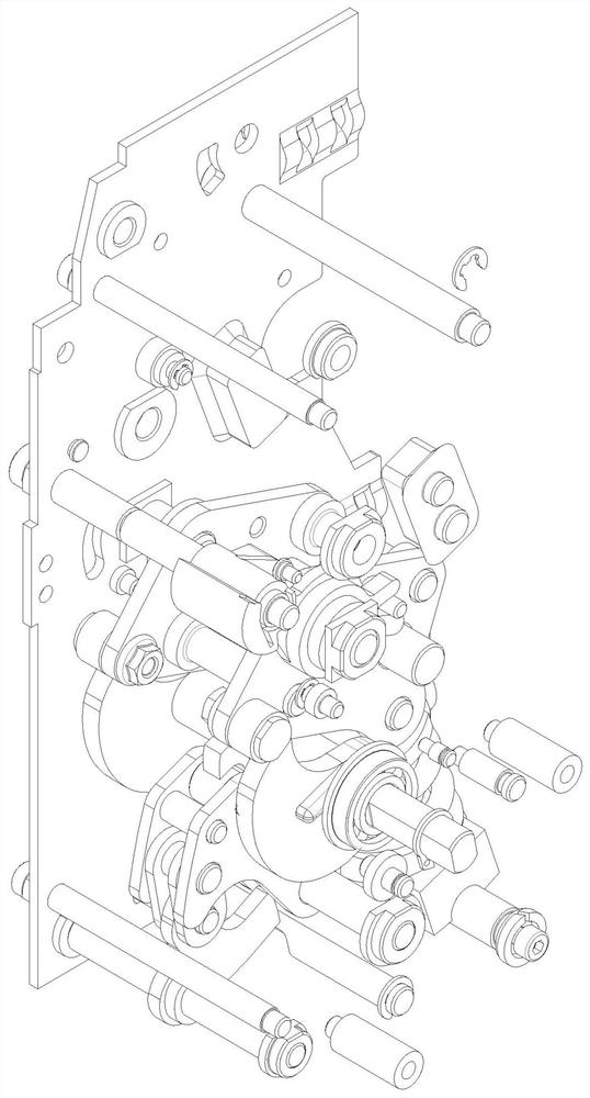
[0023] as attached figure 1 , as shown in 2 and 3, a circuit breaker energy storage indicating interlocking mechanism, including a cam 1, the cam 1 is pivotally connected to the side plate 6 through the main shaft 8. The cam 1 is linked with the roller 201 provided on the energy storage lever 2. During the rotation of the cam 1, the roller 201 can be driven to drive the energy storage lever 2 to rotate. The energy storage lever 2 is coaxially equipped with a lever 3. During the rotation of the energy storage lever 2, the linkage part 202 provided on it can drive the shift lever 3 to rotate in the same direction, and the shift lever 3 can push the energy storage indicator 4 to rotate during the rotation process to display the energy storage Or in the state of no energy storage, the energy storage indicator 4 is equipped with a reset member 5 to reset the energy storage indicator 4 after the energy storage is completed. In this embodiment, the energy storage indicating member 4...


PUM


Abstract

The invention provides a circuit breaker energy storage indication interlocking mechanism, which comprises a cam (1), wherein the cam (1) is in linkage with a roller (201) arranged on an energy storage lever (2), the cam (1) can drive the roller (201) to drive the energy storage lever (2) to rotate in the rotating process, the energy storage lever (2) is coaxially provided with a shifting rod (3), the energy storage lever (2) can drive the shifting rod (3) to rotate in the same direction through a linkage part (202) arranged on the energy storage lever (2) in the rotating process, and the shifting rod (3) can push an energy storage indicating piece (4) to rotate in the rotating process so as to display the energy storage state or the non-energy-storage state. According to the circuit breaker energy storage indication interlocking mechanism, the replaceability of the circuit breaker energy storage indication interlocking mechanism is improved, the maintenance difficulty is reduced, the speed is low during energy storage, the impact on the energy storage indication piece is small, the shifting rod rotates anticlockwise during energy release, the energy storage indication piece automatically resets under the action of the energy storage reset piece so as to switch indication, the impact is small, and the whole structure prolongs the service life of the energy storage indicating piece.

Description

technical field [0001] The invention relates to the technical field of circuit breakers, in particular to a circuit breaker energy storage indicating interlocking mechanism. Background technique [0002] Circuit breakers are divided into high-voltage circuit breakers and low-voltage circuit breakers according to their scope of use. Low-voltage circuit breaker, also known as automatic switch, commonly known as "air switch", also refers to low-voltage circuit breaker. It is an electrical appliance that not only has the function of manual switch, but also can automatically protect against voltage loss, undervoltage, overload, and short circuit. It can be used to distribute electric energy, start asynchronous motors infrequently, protect power lines and motors, etc., and can automatically cut off the circuit when they have severe overload, short circuit and undervoltage faults. Its function is equivalent to a fuse switch and The combination of overheating and underheating relay...

Claims


Application Information

Patent Timeline
Patent Type & Authority Applications(China)
IPC IPC(8): H01H3/30H01H71/04H01H71/10
CPCH01H3/3015H01H71/04H01H71/1009H01H2003/3073
Inventor 何春曹林周盛阳
Owner SHANGHAI LIANGXIN ELECTRICAL
Learn More