
Sea-land connector box for low-temperature environment and installation method

A low-temperature environment, joint box technology, applied in the direction of light guide, optics, instruments, etc., to achieve the effect of increasing tensile strength, isolating water vapor, and increasing tensile strength

Pending Publication Date: 2022-01-04
中航宝胜海洋工程电缆有限公司
View PDF0 Cites 0 Cited by
  • Summary
  • Abstract
  • Description
  • Claims
  • Application Information

AI Technical Summary

Problems solved by technology

[0006] The purpose of the present invention is to overcome the structural shortcomings of the existing splice box, solve the problem of using the sea-land splice box in an extremely low temperature environment, while ensuring the sealing performance of the sea-land splice box, strengthen the tensile strength of the optical cable, and reduce the difficulty of integration. Protect the port cable

Method used


Image

  • Sea-land connector box for low-temperature environment and installation method
  • Sea-land connector box for low-temperature environment and installation method
  • Sea-land connector box for low-temperature environment and installation method

Examples


Embodiment 1

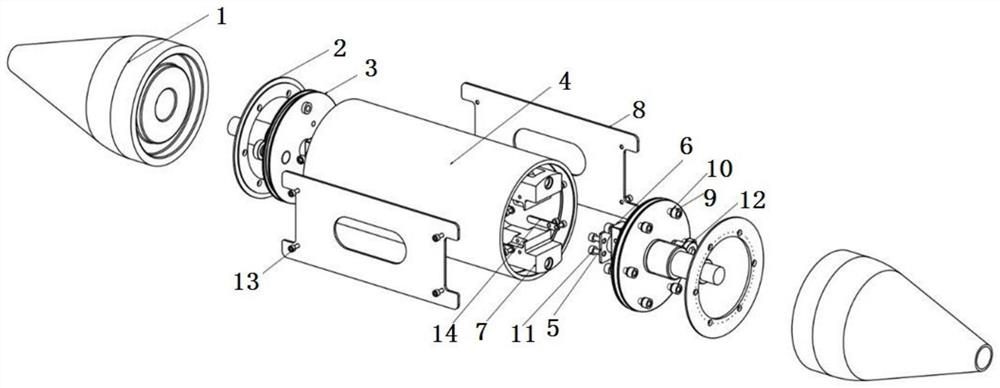
[0050] Such as figure 1 , 2As shown in , 5, the sea-land joint box for low temperature environment includes a fiber optic box 7, a pressure-resistant cylinder 4 and sealing end caps 3 at both ends of the pressure-resistant cylinder. The sealed end cover at the end is connected into the fiber optic box; the sealing process is performed between the sealed end cover and the pressure-resistant cylinder, and between the sealed end cover and the optical cable. Oil plug plug 12 is arranged.

[0051] The outer surfaces of the two sealed end caps are respectively provided with cable end protective sleeves 1, and the interior of the cable end protective sleeves is provided with a through hole for the optical cable to pass through. The outer surface of the sealed end caps is provided with an extension 19. The end protection sleeve is screwed into one body through the extension part and the through hole. The contact surface between the extension part and the inner wall of the through h...

Embodiment 2

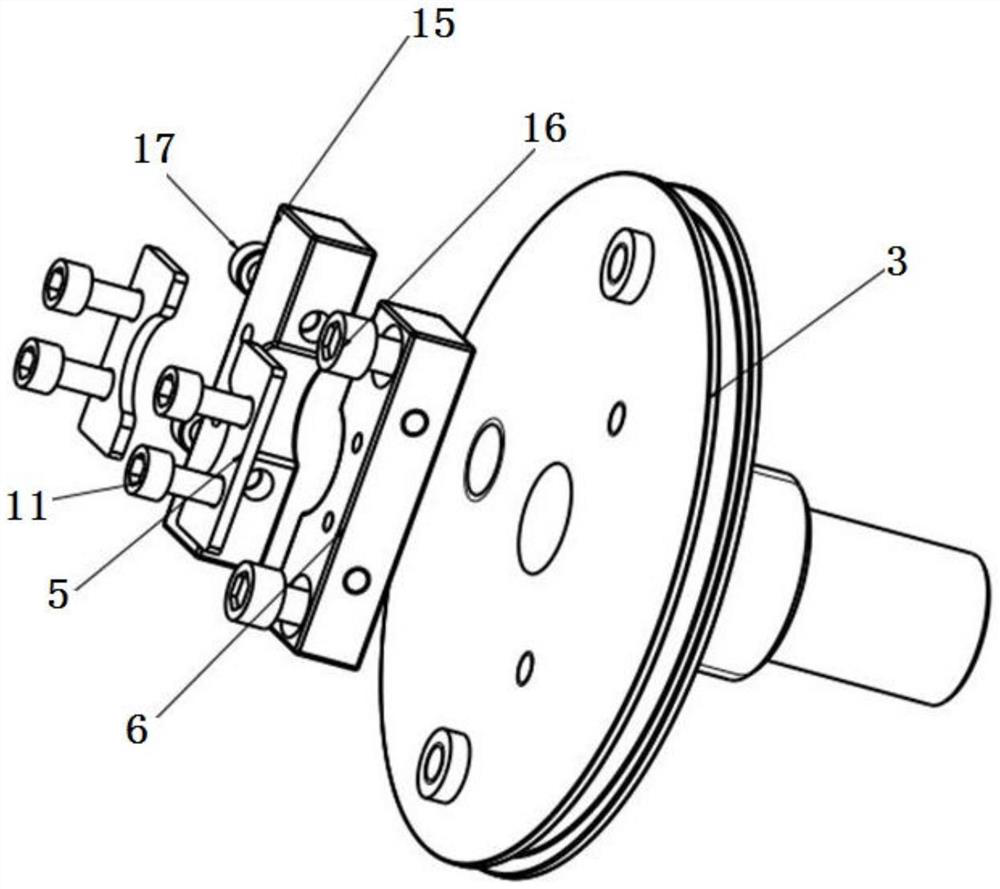
[0059] On the basis of Example 1, such as image 3 As shown, there is an optical cable fixing device inside the sealing end cover, including a cable end fixing piece 6, a cable end locking piece 15, and two anchor pieces 5; the cable end fixing piece, the cable end locking piece, and the anchor piece are in contact with the optical cable There are curved grooves everywhere.

[0060] The cable end fixing part and the cable end locking part are in a half-open structure. The cable end fixing part is fixed on the inner side of the sealing end cover through the fixing screw 16, and the cable end locking part is connected with the cable end fixing part through the locking screw 17. Co-clamping secures the fiber optic cable.

[0061] Similarly, the two anchors have a half-open structure, and the two anchors anchor the cable armored steel wire layer between the cable end fixing piece, the outer surface of the cable end locking piece and the corresponding anchoring pieces through the ...

Embodiment 3

[0064] Such as figure 1 , 2 As shown, the end surface of the protective sleeve of the pressure-resistant cylinder is provided with a groove matching the locking screw of the limit ring to form a limit step surface for matching with the oil plug plug. The stopper is used to limit the position and enhance the sealing performance of the oil filling port.


PUM


Abstract

The invention relates to a sea-land connector box for a low-temperature environment and an installation method, and belongs to the field of optical cable communication. The sea-land connector box comprises a fiber coiling box, a compression-resistant cylinder and sealing end covers at the two ends of the compression-resistant cylinder, the fiber coiling box is located in the compression-resistant cylinder, and an optical cable penetrates through the sealing end covers at the two ends of the compression-resistant cylinder to be connected into the fiber coiling box; sealing treatment is carried out between the sealing end cover and the compression-resistant cylinder and between the sealing end cover and the optical cable, and low-temperature optical fiber filling ointment is injected into the compression-resistant cylinder. According to the invention, the connector box is not restrained to be only laid in a manhole, the compressive strength is greatly enhanced, the problem that the use environment of the traditional sea-land joint box is limited is solved, and the cable end and the internal structure are safer and more reliable.

Description

technical field [0001] The invention relates to a sea-land joint box for a low-temperature environment and an installation method, belonging to the field of optical cable communication. Background technique [0002] The optical cable splice box is a connection protection device provided for the optical, sealing and mechanical strength continuity of each optical cable when the structural optical cables are connected and branched between overhead, pipeline, direct burial and other laying methods. Nowadays, as communication is becoming more and more important in production and life, the use of optical cable splice boxes is also increasing. But the existing optical cable splice box also has the following deficiencies: [0003] 1. The commonly used sea and land joint boxes cannot meet the extreme low temperature environment (minus 60°C), and their use is limited; [0004] 2. When the commonly used sea and land joint boxes meet the basic functions of the appeal, they often use h...

Claims


Application Information

Patent Timeline
Patent Type & Authority Applications(China)
IPC IPC(8): G02B6/44
CPCG02B6/4446G02B6/443G02B6/44384
Inventor 刘磊胡哲伍刚陈大勇杨庆叶子豪
Owner 中航宝胜海洋工程电缆有限公司
Learn More