Eureka AIR delivers breakthrough ideas for toughest innovation challenges, trusted by R&D personnel around the world.

Ozone and nitrogen oxide separation detection method and device

A technology of nitrogen oxides and detection devices, which is applied in the direction of material excitation analysis, color/spectral characteristic measurement, fluorescence/phosphorescence, etc., can solve problems such as interference with the ozone detection process, and achieve the effect of avoiding impurities from interfering with the detection process and facilitating disassembly and cleaning

Pending Publication Date: 2022-01-04
湖南云界科技服务有限公司
View PDF6 Cites 0 Cited by
  • Summary
  • Abstract
  • Description
  • Claims
  • Application Information

AI Technical Summary

Problems solved by technology

[0003] The purpose of the present invention is to provide a method and device for separation and detection of ozone and nitrogen oxides, which solves the problem that the detection process of nitrogen oxides interferes with the detection process of ozone in the prior art

Method used


Image

  • Ozone and nitrogen oxide separation detection method and device
  • Ozone and nitrogen oxide separation detection method and device
  • Ozone and nitrogen oxide separation detection method and device

Examples


Embodiment 1

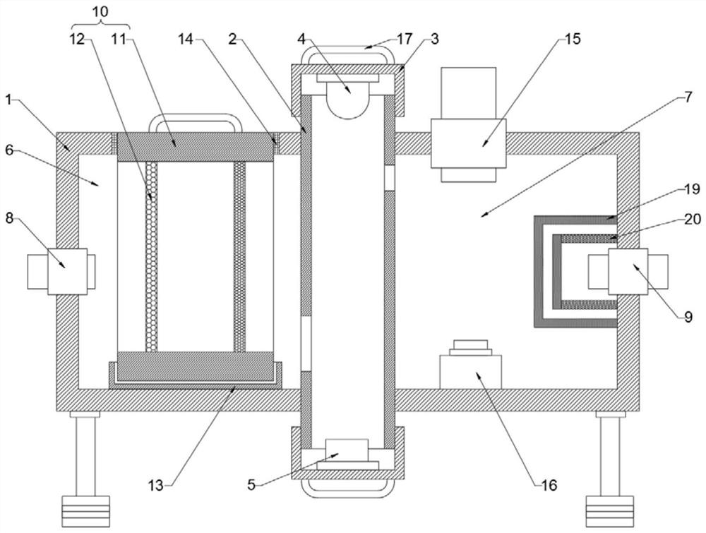
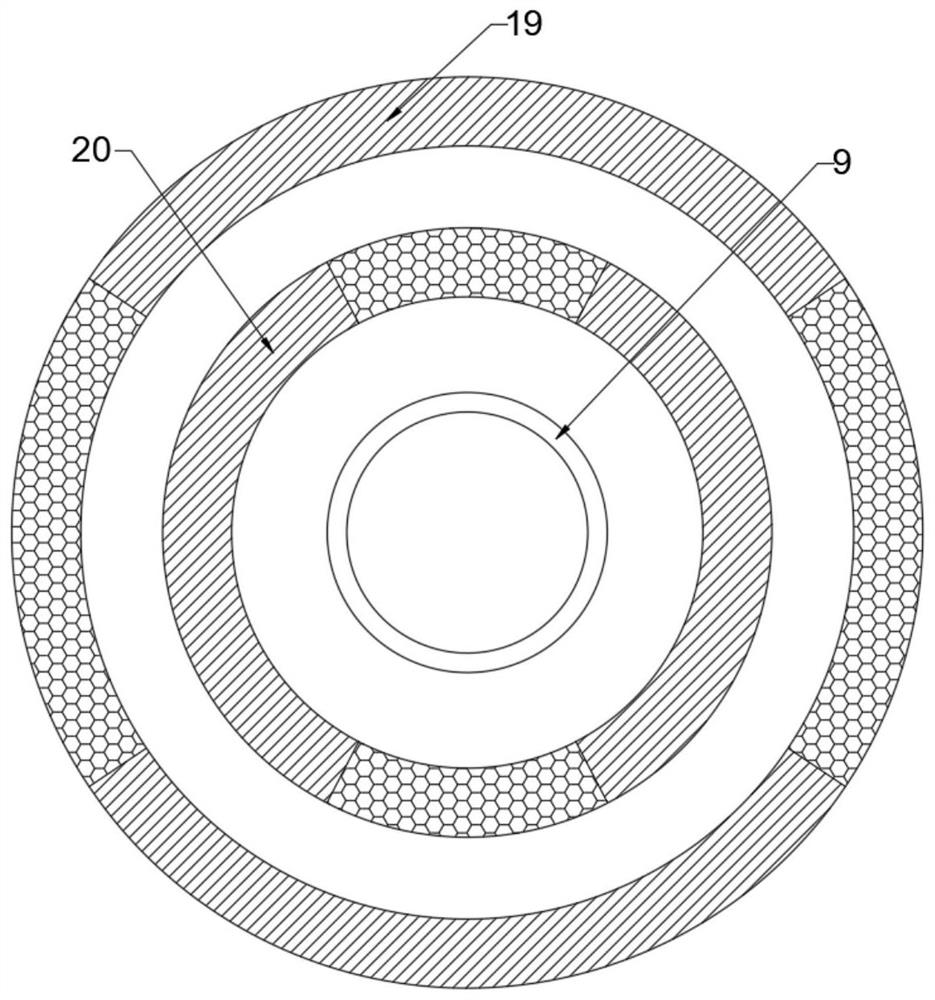
[0026] refer to Figure 1-3 , a separation and detection device for ozone and nitrogen oxides, comprising an outer box 1, the bottom of the outer box 1 is fixedly connected with four support feet distributed in a rectangular array, and the inside of the outer box 1 is provided with a detection cylinder 2, and the detection cylinder 2 It is fixedly connected with the outer box 1, the top and bottom ends of the detection cylinder 2 both pass through the outer box 1 and have an open structure, both sides of the detection cylinder 2 are fixedly connected with partitions 21, and the top and bottom of the detection cylinder 2 are installed There are mounting bases 3, a purple light generating device 4 is installed on the inner side of one mounting base 3, and a light sensor 5 is installed on the inner side of the other mounting base 3. One side of the detection cylinder 2 fits and is fixedly connected with the side wall of the outer box 1. The detection cylinder 2 and the partition ...

Embodiment 2

[0036] refer to Figure 1-3 , a separation and detection device for ozone and nitrogen oxides, comprising an outer box 1, the bottom of the outer box 1 is fixedly connected with four support feet distributed in a rectangular array, and the inside of the outer box 1 is provided with a detection cylinder 2, and the detection cylinder 2 It is fixedly connected with the outer box 1, the top and bottom ends of the detection cylinder 2 both pass through the outer box 1 and have an open structure, both sides of the detection cylinder 2 are fixedly connected with partitions 21, and the top and bottom of the detection cylinder 2 are installed There are mounting bases 3, a purple light generating device 4 is installed on the inner side of one mounting base 3, and a light sensor 5 is installed on the inner side of the other mounting base 3. One side of the detection cylinder 2 fits and is fixedly connected with the side wall of the outer box 1. The detection cylinder 2 and the partition ...


PUM


Abstract

The invention relates to the technical field of gas detection, in particular to an ozone and nitrogen oxide separation detection method and device, and solves the problem that the detection process of nitrogen oxide excessively interferes with the detection process of ozone in the prior art. The ozone and nitrogen oxide separation detection device comprises an outer box, the bottom of the outer box is fixedly connected with four supporting foot bases which are distributed in a rectangular array, a detection cylinder is arranged in the outer box and fixedly connected with the outer box, and the top end and the bottom end of the detection cylinder both penetrate through the outer box and are each of an opening structure, partition plates are fixedly connected to the two sides of the detection cylinder, mounting bases are mounted at the top and the bottom of the detection cylinder, a purple light generating device is mounted on the inner side of one mounting base, and a light sensor is mounted on the inner side of the other mounting base. According to the invention, by designing the detection process of detecting ozone first and then detecting nitrogen oxide, the effect of simultaneously detecting ozone and nitrogen oxide in the gas circulation process is realized, and the detection efficiency is effectively improved.

Description

technical field [0001] The invention relates to the technical field of gas detection, in particular to a separation and detection method and device for ozone and nitrogen oxides. Background technique [0002] China's ambient air quality standards clearly stipulate that nitrogen oxides and ozone are basic pollutants. Therefore, it is necessary to detect the content of ozone and nitrogen oxides in various types of gases produced in daily life and industrial production. Among them, the detection of ozone is mostly The ultraviolet spectrophotometry method is used to detect nitrogen oxides, and the chemiluminescence method is often used. When detecting nitrogen oxides, a large amount of ozone needs to be mixed in the sample gas, so that ozone and nitrogen monoxide can undergo a chemical reaction to generate excited state NO2, and then Photons can be released during the process of detecting NO2 returning to the ground state, so the existing detection devices cannot detect ozone an...

Claims


Application Information

Patent Timeline
Patent Type & Authority Applications(China)
IPC IPC(8): G01N21/33G01N21/64
CPCG01N21/33G01N21/64Y02A50/20
Inventor 刘超
Owner 湖南云界科技服务有限公司
Why Eureka
Eureka Blog
Learn More