Flue gas bypass adjusting equipment for boiler economizer

A technology of flue gas bypass and regulating equipment, which is applied in the field of boiler economizer, which can solve the problems of low load, waste of catalyst, and reduction of out-of-stock effect, and achieve the effects of reducing NOx emissions, improving full response, and reducing labor costs

Pending Publication Date: 2022-01-04
HUANENG CHAOHU POWER GENERATION
View PDF0 Cites 1 Cited by
  • Summary
  • Abstract
  • Description
  • Claims
  • Application Information

AI Technical Summary

Problems solved by technology

[0003] When the out-of-stock treatment is carried out in the boiler, because the temperature of the original flue gas is not high, it is easy to produce a low-load situation. When the out-of-stock treatment is performed under a low-load state, the flue gas and the catalyst cannot be fully reacted, which in turn causes the out-of-stock treatment. Reduced effect, no better reduction of NOx emissions
[0004] The currently used bypass flue gas is used to heat the inside of the boiler to increase the temperature of the flue gas in the boiler, but the temperature cannot be obtained according to the needs, and the temperature of the flue gas inside will often be too high, which will reduce the out-of-stock effect. In the boiler When the temperature of the flue gas is not raised to a suitable temperature, adding a catalyst for catalysis will cause a waste of the catalyst. Therefore, a boiler economizer flue gas bypass adjustment device is proposed

Method used


Image

  • Flue gas bypass adjusting equipment for boiler economizer
  • Flue gas bypass adjusting equipment for boiler economizer
  • Flue gas bypass adjusting equipment for boiler economizer

Examples


Embodiment Construction

[0030] The following will clearly and completely describe the technical solutions in the embodiments of the present invention with reference to the accompanying drawings in the embodiments of the present invention. Obviously, the described embodiments are only some, not all, embodiments of the present invention.

[0031] A flue gas bypass adjustment device for a boiler economizer, comprising:

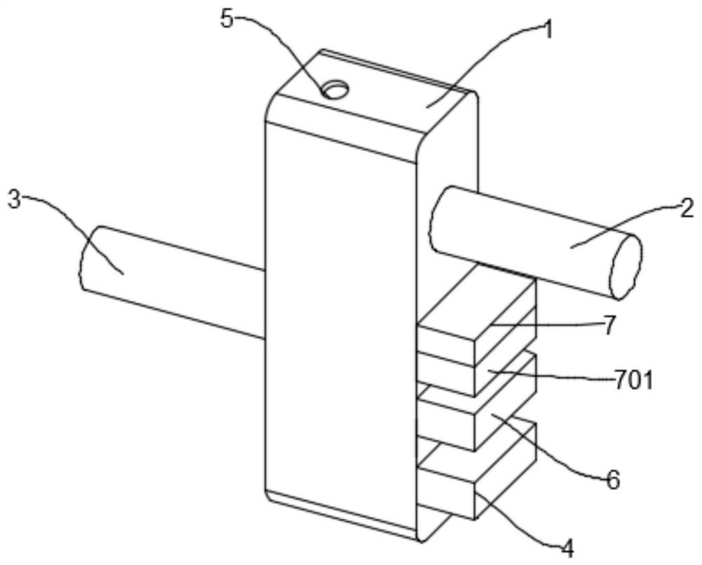
[0032] Such as figure 1 As shown, the boiler 1, the side of the boiler 1 is fixedly connected with the gas transmission pipe 2 for inputting flue gas, the side of the boiler 1 away from the boiler 1 is fixedly connected with the outlet pipe 3 for outputting flue gas, and the top and bottom of the boiler 1 are equipped with The gas delivery port 5 for inputting flue gas;

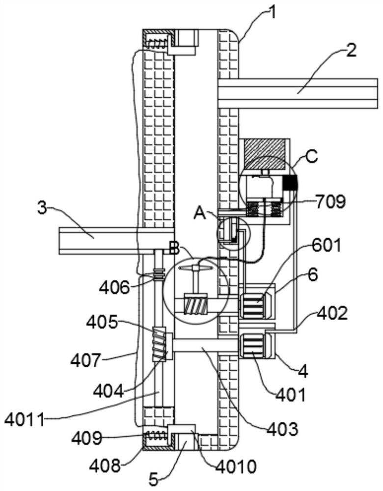
[0033] An automatic switch mechanism, the automatic switch mechanism for automatically opening and closing the first motor 401 is located on one side of the boiler 1;

[0034] Rotary closing mechanism, the rotary clo...


PUM


Abstract

The invention discloses flue gas bypass adjusting equipment for a boiler economizer. The flue gas bypass adjusting equipment comprises a boiler, an automatic opening and closing mechanism, a rotary closing mechanism and a rotary spraying mechanism, wherein one side of the boiler is fixedly connected with a gas conveying pipe for inputting flue gas, the side, away from the boiler, of the boiler is fixedly connected with a gas outlet pipe for outputting flue gas, and the top and the bottom of the boiler are each provided with a gas conveying opening for inputting flue gas; the automatic opening and closing mechanism is used for automatically opening and closing a first motor and is located on one side of the boiler; the rotary closing mechanism is used for opening and closing the gas conveying openings and is located below the automatic opening and closing mechanism; and the rotary spraying mechanism is used for spraying a catalyst and is located above the rotary closing mechanism. By means of the automatic opening and closing mechanism, the rotary closing mechanism and the rotary spraying mechanism, the catalyst is used for catalysis when the temperature in the boiler reaches the catalytic temperature, on one hand, the denitration effect is improved, and on the other hand, waste of the catalyst is reduced.

Description

technical field [0001] The invention relates to the technical field of boiler economizers, in particular to a flue gas bypass adjustment device for boiler economizers. Background technique [0002] In order to prevent excessive NOx pollution of the environment after coal combustion in the boiler, coal should be denitrified, divided into denitrification before combustion, denitrification during combustion, and denitrification after combustion. The purpose is to prevent excessive NOx pollution in the environment after coal combustion in the boiler , Coal should be denitrified, which can be divided into denitrification before combustion, denitrification during combustion, and denitrification after combustion. [0003] When the out-of-stock treatment is carried out in the boiler, because the temperature of the original flue gas is not high, it is easy to produce a low-load situation. When the out-of-stock treatment is performed under a low-load state, the flue gas and the cataly...

Claims


Application Information

Patent Timeline
Patent Type & Authority Applications(China)
IPC IPC(8): F23J15/00F23J15/04F23J15/06
CPCF23J15/003F23J15/04F23J15/06
Inventor 李延怀张敏徐龙海汪辉夏洲孙宝仁
Owner HUANENG CHAOHU POWER GENERATION
Why Eureka
Try Eureka