
Antenna assembly and terminal equipment

A technology of antenna components and antenna structures, which is applied to antenna components, antennas, slot antennas, etc., can solve problems such as difficulty in maintaining antenna MIMO performance, difficulty in adapting antennas to sub-6G antenna layout requirements, etc., to reduce headroom area, reduce Occupied area, effect of improving compactness

Pending Publication Date: 2021-12-31
ZTE CORP
View PDF0 Cites 2 Cited by
  • Summary
  • Abstract
  • Description
  • Claims
  • Application Information

AI Technical Summary

Problems solved by technology

[0003] However, 5G terminal equipment requires antennas to meet the performance of 4X4 ​​MIMO systems. In order to improve the isolation between antennas and the ECC (Envelope Correlation Coefficient) performance between antennas, the existing antenna improvement methods usually choose to pull It is difficult to maintain the MIMO performance of the antenna due to the space distance between the antennas, and it is difficult for the improved antenna to meet the layout requirements of the sub-6G antenna

Method used


Image

  • Antenna assembly and terminal equipment
  • Antenna assembly and terminal equipment
  • Antenna assembly and terminal equipment

Examples


Embodiment Construction

[0030] Specific embodiments of the present disclosure will be described in detail below in conjunction with the accompanying drawings. It should be understood that the specific embodiments described here are only used to illustrate and explain the present disclosure, and are not intended to limit the present disclosure.

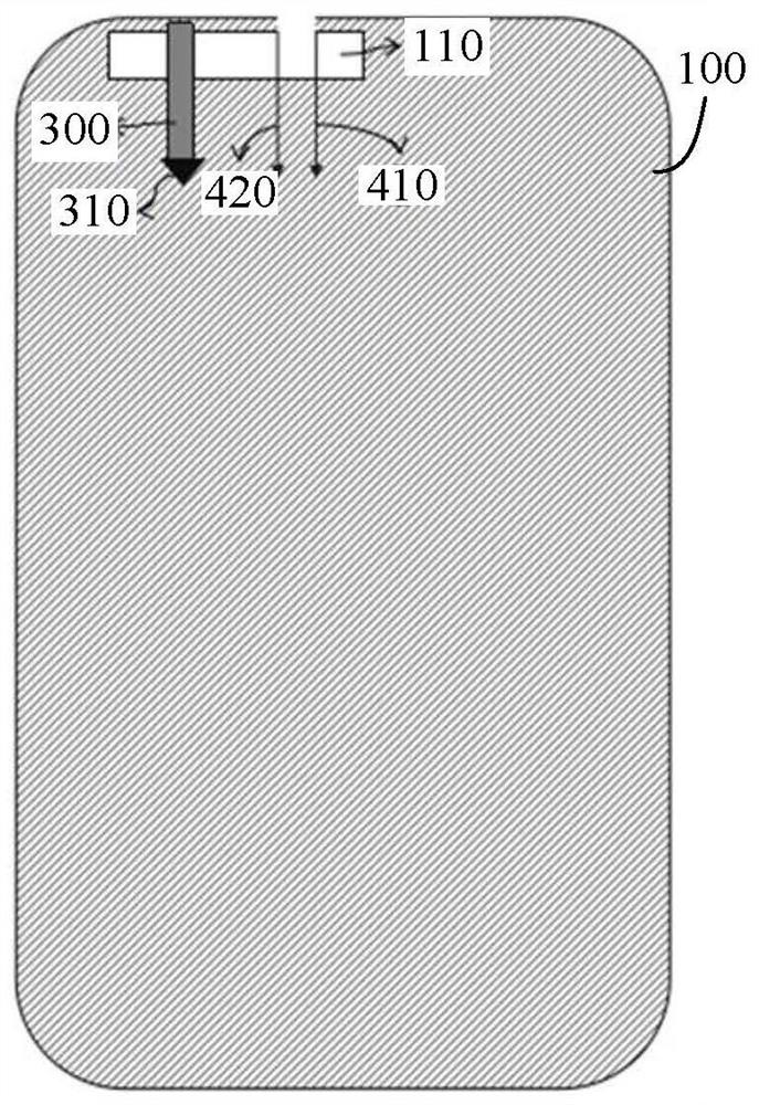
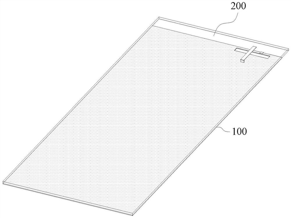
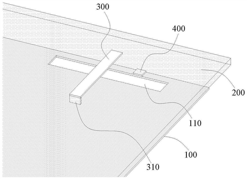
[0031] As an aspect of the present disclosure, an antenna assembly is provided, such as Figure 1 to Figure 4 As shown, the antenna assembly includes a circuit board and at least one antenna structure disposed on the circuit board. Wherein, the circuit board includes a conductive floor 100 , and at least one emission slot hole 110 penetrating through the conductive floor 100 along the thickness direction is formed on the conductive floor 100 . The antenna structure includes a feeding stub 300 and a feeding part 400. The position of the feeding stub 300 matches the emitting slot 110, and is used to excite the emitting slot 110 to generate slotted antenna radi...


PUM


Abstract

The invention provides an antenna assembly. The antenna assembly comprises a circuit board and at least one antenna structure arranged on the circuit board, wherein the circuit board comprises a conductive floor, at least one transmitting slot hole penetrating through the conductive floor in the thickness direction is formed in the conductive floor, the antenna structure comprises a feed branch knot and a feed part, the feed branch knot is matched with the transmitting slot hole in position and is used for exciting the transmitting slot hole to generate slotted antenna radiation, and the feed part is arranged at the edge of the transmitting slot hole and is used for driving the transmitting slot hole to generate loop antenna radiation. According to the antenna assembly, the same transmitting slot hole in the conductive floor in the antenna assembly is used for manufacturing the two antenna units, so that the two antenna units share the same antenna area on the circuit board, the clearance area of the antenna structure is reduced while the MIMO performance of the antenna is maintained, and the compactness of the terminal equipment structure is improved. The invention further provides terminal equipment.

Description

technical field [0001] The present disclosure relates to the field of electronic equipment, in particular, to an antenna assembly and a terminal equipment Background technique [0002] With the rapid development of the field of smart terminal equipment, 5G mobile phones have become the focus of competition among major terminal manufacturers, and the communication advantages of 5G mobile phones benefit from the powerful signal sending and receiving capabilities of their 5G antennas. Existing 5G antennas usually use MIMO (MultiInput Multi Output) antenna technology, requiring more than a dozen antennas to be arranged inside the mobile phone. [0003] However, 5G terminal equipment requires antennas to meet the performance of 4X4 ​​MIMO systems. In order to improve the isolation between antennas and the ECC (Envelope Correlation Coefficient) performance between antennas, the existing antenna improvement methods usually choose to pull It is difficult to maintain the MIMO perfor...

Claims


Application Information

Patent Timeline
Patent Type & Authority Applications(China)
IPC IPC(8): H01Q1/24H01Q1/36H01Q1/38H01Q1/48H01Q1/50H01Q5/307H01Q13/10H01Q21/00H04B7/0413
CPCH01Q1/242H01Q1/36H01Q1/38H01Q1/48H01Q1/50H01Q5/307H01Q13/10H01Q21/00H04B7/0413H01Q7/00H01Q1/243H01Q21/28H01Q5/35H01Q13/106
Inventor 杨世榕
Owner ZTE CORP
Learn More