
Tea bar machine and refrigerating system control method based on tea bar machine

A technology of refrigeration system and control method, which is applied in the direction of household refrigeration equipment, coolers, beverage preparation equipment, etc., and can solve the problems of high energy consumption, difficulty in achieving the best start-stop ratio of compressors, and difficulty in meeting the function of ice water, etc., to achieve Improve safety, ensure no freezing, and reduce energy consumption

Pending Publication Date: 2021-12-31
CHANGHONG MEILING CO LTD
View PDF11 Cites 0 Cited by
  • Summary
  • Abstract
  • Description
  • Claims
  • Application Information

AI Technical Summary

Problems solved by technology

[0005] The purpose of the present invention is to provide a tea bar machine, which can realize the refrigeration demand under high ambient temperature by adopting the compressor refrigeration method and setting the ice water chamber, and solve the problem that the existing common electronic refrigeration method cannot meet the refrigeration temperature requirement , and the problem that it is difficult to meet the function of ice water
[0006] Another object of the present invention is to provide a refrigeration system control method based on a tea bar machine. By matching the temperature T1 of the refrigerating room and the temperature T2 of the ice water room with the conditions for starting and stopping the compressor respectively, the problem of starting and stopping the compressor is solved. It is difficult to achieve the best stop ratio and the problem of high energy consumption

Method used


Image

  • Tea bar machine and refrigerating system control method based on tea bar machine
  • Tea bar machine and refrigerating system control method based on tea bar machine
  • Tea bar machine and refrigerating system control method based on tea bar machine

Examples


Embodiment 1

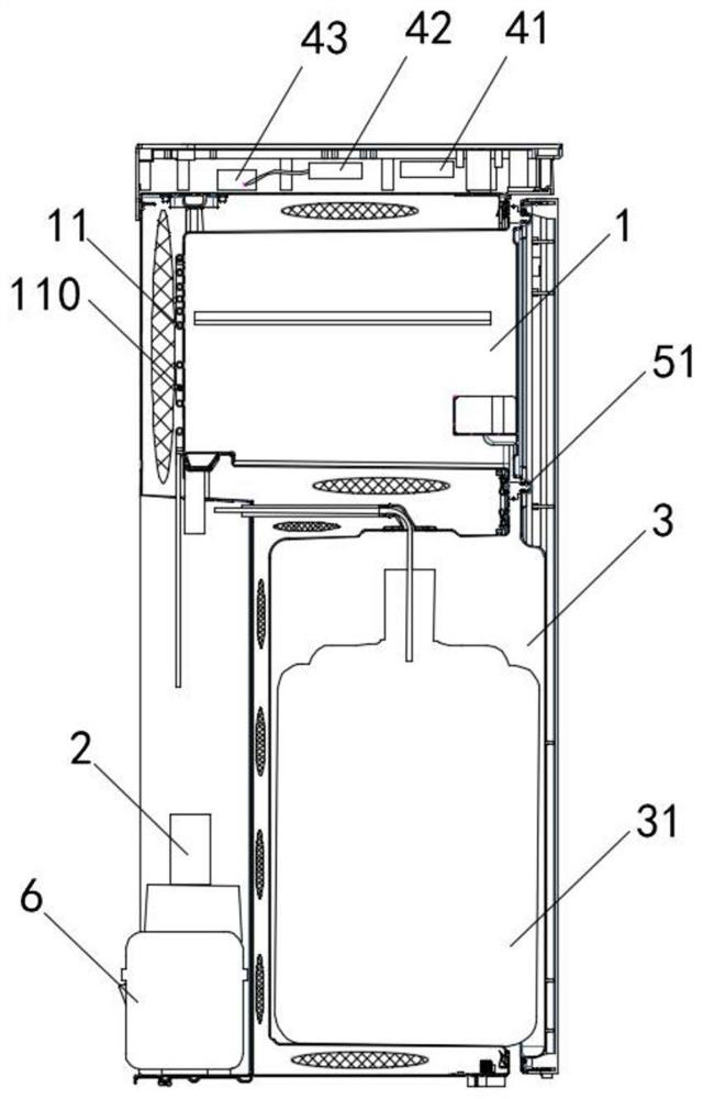
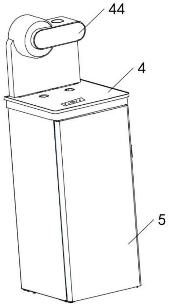
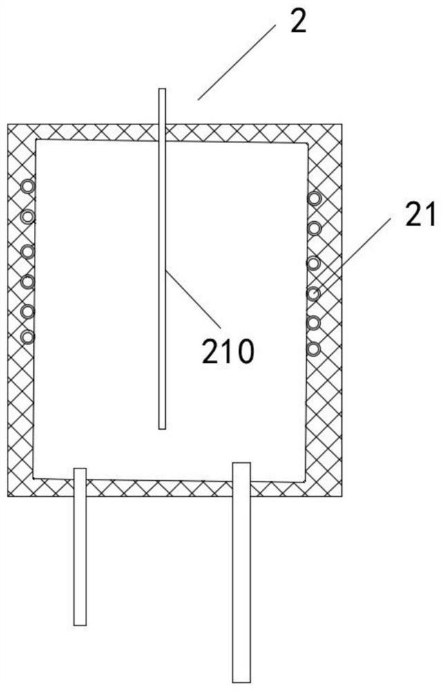
[0039] see figure 1 As shown, the present invention is a tea bar machine, including a refrigerator compartment 1, a first evaporator 11 is arranged on the rear wall of the refrigerator compartment 1, and a first temperature for collecting the temperature T1 of the refrigerator compartment 1 is arranged on the first evaporator 11. Sensor 110, the refrigerating room 1 has cooling capacity to realize the refrigerating function, the first evaporator 11 is connected to the evaporator plate, the first temperature sensor 110 indirectly obtains the temperature T1 of the refrigerating room 1 through the evaporator plate; the ice water room 2, the ice water room The second evaporator 21 is arranged on the 2 sides. By setting the ice water chamber 2, the problem that the tea bar machine in the prior art is difficult to meet the ice water function is solved. The second temperature sensor 210 is installed in the chamber 2 to collect the temperature T2 of the ice water chamber 2. Precise te...

Embodiment 2

[0045] On the basis of the above embodiments, the present invention also provides a method for controlling a refrigeration system based on a tea bar machine, including the following steps:

[0046] S01, collecting the temperature of the refrigerator compartment 1 and the ice water chamber 2; in step S01, the following steps are included: collecting the temperature T1 of the refrigerator chamber 1 through the first temperature sensor 110, and collecting the temperature T2 of the ice water chamber 2 through the second temperature sensor 210;

[0047] S02, matching the temperature collected in step S01 with the preset condition; step S02 includes the following steps: comparing the temperature T1 of the refrigerating room 1 through the collection with the preset target temperature Q1 of the refrigerating room 1, and collecting The temperature T2 of the ice water chamber 2 is compared with the preset target temperature Q2 of the ice water chamber 2;

[0048] S03, determine the star...

Embodiment 3

[0055] On the basis of the above examples, if Figure 5-6 As shown, it is judged whether the temperature T1 of the refrigerating chamber 1 is lower than the lower limit temperature Q12 of refrigerating, and if T1<Q12, the compressor 6 is forcibly shut down; it is judged whether the temperature T2 of the ice water chamber 2 is lower than the lower limit temperature Q22 of the ice water, in this embodiment Set it to 4°C, which is the critical point of ice water. If T2<Q22, the compressor 6 will be forced to shut down; judge whether the continuous power-on time of the compressor 6 exceeds the limit value. Here, the continuous power-on time limit is set to 1 hour. If so, then Compressor 6 is forced to shut down.


PUM


Abstract

The invention discloses a tea bar machine, and relates to the technical field of refrigeration of tea bar machines. The tea bar machine comprises a refrigerating chamber, an ice water chamber and a compressor, a first evaporator is arranged on the rear wall of the refrigerating chamber, and a first temperature sensor is arranged on the first evaporator. A second evaporator is arranged on the peripheral side of the ice water chamber, and a second temperature sensor is arranged in the ice water chamber. The first evaporator and the second evaporator are sequentially connected in series to form a refrigerating system. The compressor is arranged in the tea bar machine. According to the tea bar machine, the compressor refrigeration mode is adopted, and the problem that an existing electronic refrigeration mode cannot meet the refrigeration temperature requirement is solved. The invention further provides a refrigerating system control method based on the tea bar machine. The refrigerating system control method comprises the following steps that S01, the temperature of the refrigerating chamber and the temperature of the ice water chamber are collected; S02, the temperature collected in the S01 is matched with a starting condition; and S03, the starting and stopping conditions of the compressor are determined. By optimizing the temperature control rule, the problem that the start-stop ratio of an existing compressor is difficult to reach the best is solved.

Description

technical field [0001] The invention belongs to the technical field of tea bar machine refrigeration, in particular to a tea bar machine and a refrigeration system control method based on it. Background technique [0002] Existing tea bar machine, cabinet part generally has two compartments, and one is storage room, mainly stores articles such as tealeaves, coffee, and another compartment provides space for storage of bucket. [0003] The utility model patent with the publication number CN2305628 discloses a water dispenser with a freezer, which includes a water dispenser and a freezer. The water dispenser and the freezer share a series-connected double-throttling refrigeration system. The capillary tube and two groups of evaporators, one group of evaporators are placed on the periphery of the ice water tank, and the other evaporator is placed in the freezing chamber on the top of the freezer. This patent adopts a compressor refrigeration method to cool the ice water tank a...

Claims


Application Information

Patent Timeline
Patent Type & Authority Applications(China)
IPC IPC(8): F25D11/02F25D23/12F25D29/00A47J31/44
CPCF25D11/022F25D23/126F25D29/00A47J31/44F25D2600/06
Inventor 程春明马长州
Owner CHANGHONG MEILING CO LTD
Learn More