
Radiator, engine cooling system with same and engine

An engine cooling and radiator technology, applied in engine cooling, machine/engine, engine components, etc., can solve problems such as easy jamming of electric push rods, high temperature of heaters, and poor reliability.

Pending Publication Date: 2021-12-31
JIANGSU WORLD AGRI MACHINERY
View PDF0 Cites 0 Cited by
  • Summary
  • Abstract
  • Description
  • Claims
  • Application Information

AI Technical Summary

Problems solved by technology

[0005] Therefore, the technical problem to be solved in the present invention is to overcome the prior art, when the impurities adsorbed on the grille of the engine radiator are removed, when the brush rotates, the fine dust will enter through the small holes on the dustproof grille. The heat dissipation core of the water tank affects the heat dissipation of the water tank, leads to high temperature of the heater, affects the performance of the engine, and another kind of electric push rod is easy to get stuck when the electric push rod is used to change the angle of the fan blade to blow off the impurities on the grille , the phenomenon that the fan does not turn, the reliability is poor, which affects the heat dissipation of the water tank, causes the high temperature of the heater, and affects the performance of the engine, thus providing an effect of removing impurities on the grille, high reliability, and will not affect the heat dissipation of the water tank , which in turn makes the heat dissipation effect of the radiator good, the engine performance is stable, the radiator and the engine cooling system and the engine

Method used


Image

  • Radiator, engine cooling system with same and engine
  • Radiator, engine cooling system with same and engine
  • Radiator, engine cooling system with same and engine

Examples


Embodiment 1

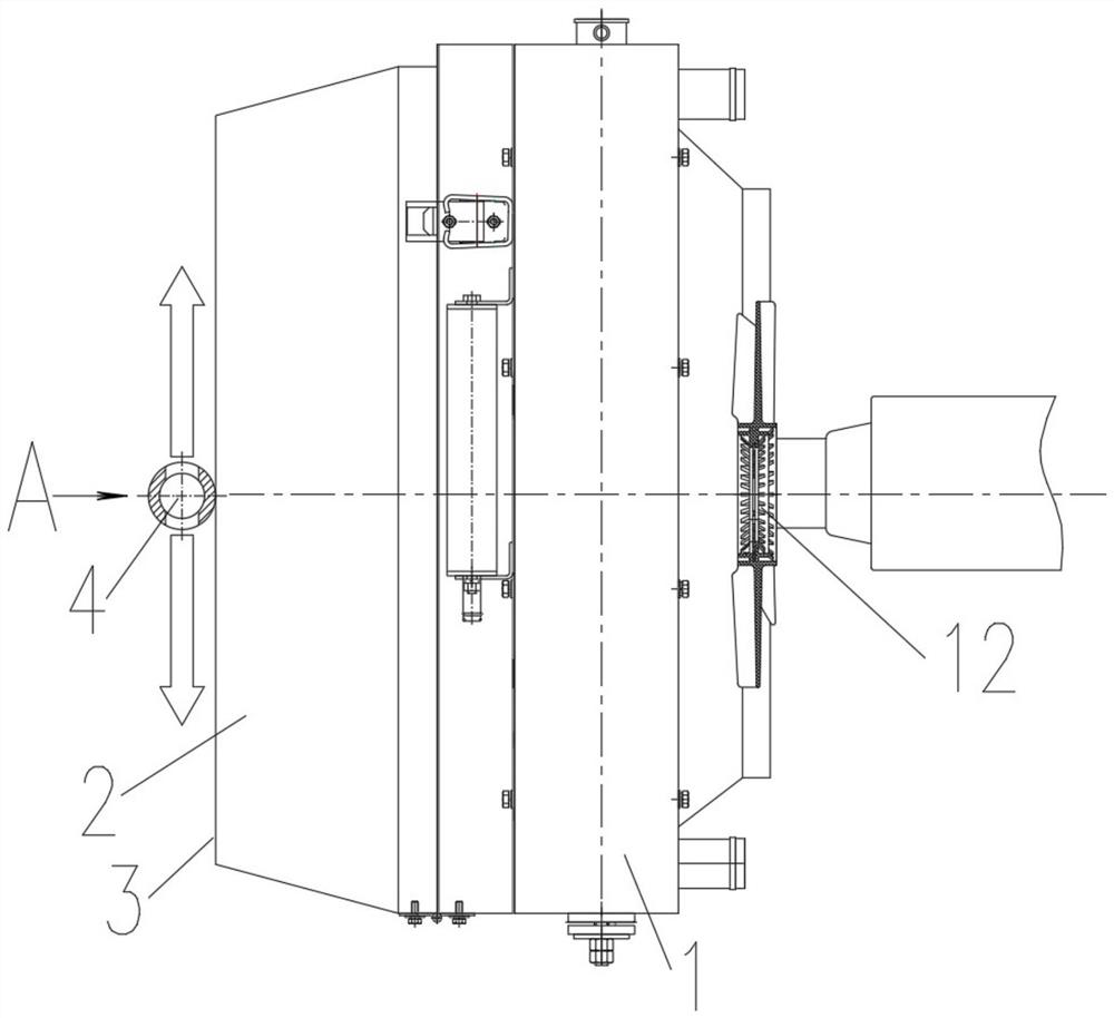
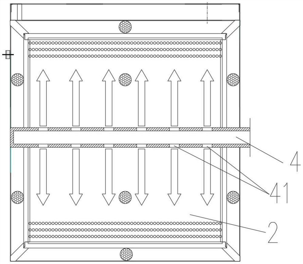
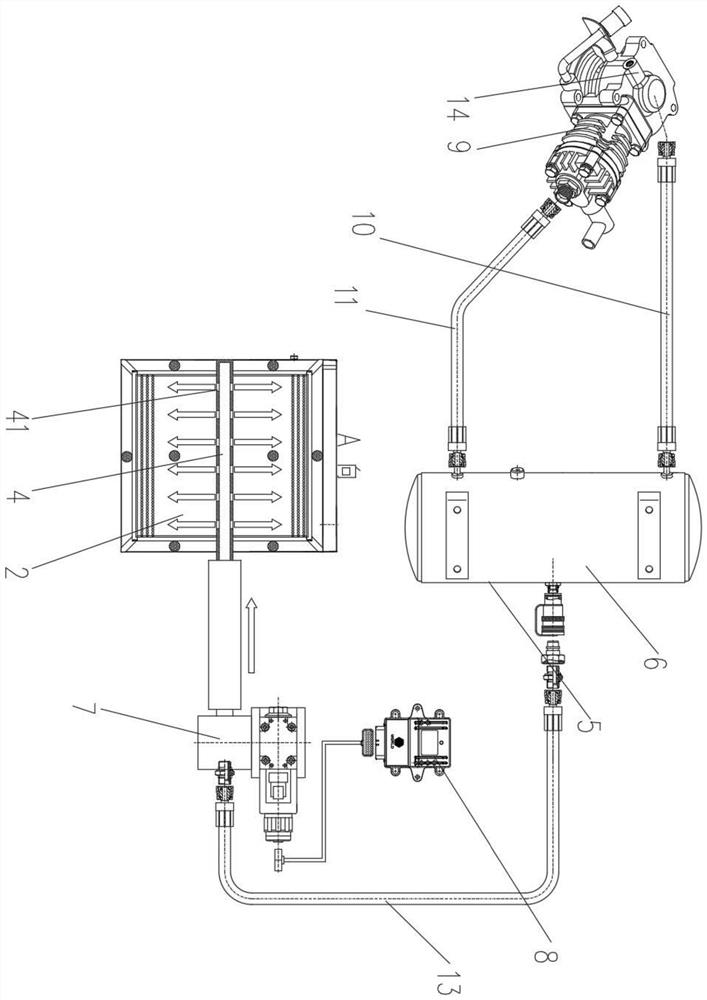
[0032] This embodiment describes a radiator, see Figure 1-Figure 3 , the radiator includes a box body 1, a net cover 2 and a cleaning device, wherein the box body 1 is a water tank, and a water circuit is arranged in it, and a fan is set on one side of the water tank, and the cooling water of the engine is cooled by using the fan. The outer side of the water tank is provided with a net cover 2, which is specifically arranged on the other side away from the fan 12 on the water tank. The net cover 2 is used to intercept the impurities adsorbed by the wind to the net cover 2 when the fan 12 cools the engine cooling water. Impurities on the intercepting surface 3, after the impurities are covered with the impurity intercepting surface 3, have a certain thickness, such as straw, bean grass and other debris, the cleaning device is used to remove impurities adsorbed on the impurity intercepting surface 3, mainly The impurity is blown away upwards and downwards along the plane direct...

Embodiment 2

[0044] This embodiment describes an engine cooling system, including a cooling circuit and the radiator described in Embodiment 1, wherein the cooling circuit circulates cooling water for the engine body, and the cooling circuit is arranged in the radiator casing 1, The engine cooling system has a good cooling effect on the engine, can be used under different working conditions, and has high reliability.

Embodiment 3

[0046] This embodiment describes an engine, which includes the engine cooling system described in Embodiment 2, and the engine can be continuously and well cooled by using the cooling system to ensure engine performance.


PUM


Abstract

The invention relates to the technical field of engine cooling, and provides a radiator, an engine cooling system with the radiator and an engine. The radiator comprises a box body, a mesh enclosure and a cleaning device, wherein the mesh enclosure is arranged on one side of the box body and detachably connected with the box body, the mesh enclosure is provided with an impurity intercepting surface, and impurities are adsorbed on the impurity intercepting surface; the cleaning device comprises at least one cleaning pipe, all the cleaning pipes are located on the outer side of the box body, a plurality of air outlets are formed in a pipe body of each cleaning pipe, pressurized gas with adjustable pressure is introduced into the cleaning pipes, and the pressurized gas is conveyed to the air outlets along the cleaning pipes and output from the air outlets; and the impurities adsorbed on the impurity intercepting surface are blown away along the plane of the impurity intercepting surface. The cleaning pipe in the cleaning device is arranged on the outer side of the box body, a plurality of air outlets are formed in the pipe body, then pressurized gas is introduced into the cleaning pipe, and impurities adsorbed on the impurity intercepting face are blown away through the pressurized gas.

Description

technical field [0001] The invention relates to the technical field of engine cooling, in particular to a radiator, an engine cooling system and an engine with the same. Background technique [0002] When the engine is working, it will generate a lot of heat. In order to ensure the normal operation of the engine, it is necessary to dissipate heat from the engine. At present, the heat dissipation of the engine generally adopts "circulating water + air cooling" to dissipate heat, that is, the cold water entering the engine through the water pump takes away the heat of the engine. When the water passes through the water tank, it is cooled by the cold wind through the core of the water tank and then enters the water pump. The cooling water tank is mostly a grid-shaped aluminum core. One side of the water tank is a suction fan, and the other side is to prevent dust and other sundries from entering. The dust-proof net cover set for the core of the water tank, when the engine is wo...

Claims


Application Information

Patent Timeline
Patent Type & Authority Applications(China)
IPC IPC(8): F01P11/00F01P11/06
CPCF01P11/00F01P11/06F01P2011/061F01P2011/065
Inventor 邢立成张俊成王志平李蕴慧
Owner JIANGSU WORLD AGRI MACHINERY
Learn More