


Quick Research
Generate reliable direction feasibility study reports for your R&D in just a few steps.

Technical Q&A
Discover and master advanced knowledge NOW. Basics, ideas, possibilities, all at once.

Find Solutions
As an expert in R&D theories, this can generate solutions to your technical problems instantly.

Evaluate Feasibility
Analyze your overall solution with one click, know your potential R&D risks in advance.

Monitor Landscape
Get weekly tech updates, stay abreast of the latest tech innovations and key insights.
Self-anchored suspension bridge construction method based on cable-stayed bridge beam forming conversion
A self-anchored suspension bridge and construction method technology, applied in cable-stayed bridges, suspension bridges, bridge forms, etc., can solve the problems of high cost of temporary piers, high risk of temporary pier collision with ships, and high rigidity requirements of temporary piers, and achieve no ship collision. The effect of risk, small change in stress, and no temporary stent cost
- Summary
- Abstract
- Description
- Claims
- Application Information
AI Technical Summary
Problems solved by technology
Method used
Image

Examples
Embodiment 1
[0049] The invention discloses a construction method of a self-anchored suspension bridge based on the conversion of a cable-stayed bridge into a girder, comprising:
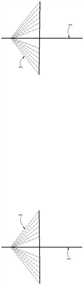
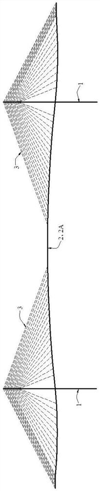
[0050] Step S1, see figure 2 , the construction forms a temporary cable-stayed bridge consisting of a cable tower 1, a main girder 2 and a plurality of temporary cable-stayed cables 3;
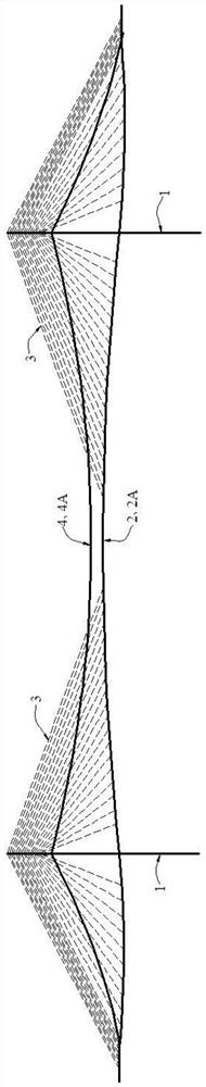
[0051] Step S2, see image 3 , according to the design drawings of the self-anchored suspension bridge, construct the main cable 4 at the corresponding positions on the cable tower 1 and the main girder 2, so that the main cable 4 is in the empty cable state 4A;
[0052] Step S3, see Figure 5 , install a corresponding number of suspenders 5 between the main cable 4 and the main girder 2 according to the installation positions of the suspenders recorded in the design drawings, and remove the temporary stay cables 3 to form the main girder 2 Self-anchored suspension bridges in bare beam state 2B;
[0053] Wherein, the install...
Embodiment approach
[0072] Such as Figure 4 As shown, in the step S3, the installation of the suspender 5 and the removal of the temporary stay cable 3 are carried out in the following manner:
[0073] Divide the main girder 2 into a plurality of sections S along the length direction, and perform operations on each section S, and when performing operations on any one of the sections S, first install the boom 5 located in the section S, and then dismantle it. Temporary stay cables 3 located in the section S;
[0074]In addition, each section S can be operated in any order, but it needs to meet the safe operation conditions: before performing any operation on any of the sections S, first calculate the number of times the main beam 2 installs the suspender 5 in the section S. The maximum negative bending moment of the main beam received is recorded as the maximum negative bending moment of the second main beam. If the maximum negative bending moment of the second main beam exceeds the safety thres...
Embodiment 3
[0078] On the basis of the above-mentioned embodiment 1 or embodiment 2, this embodiment 3 also adopts the following preferred implementation modes:
[0079] Such as figure 1 with figure 2 As shown, in the step S1, after the construction of the cable tower 1 is completed, the main girder 2 and temporary cable-stayed cables 3 are constructed by the cantilever assembly method to form the temporary cable-stayed bridge. Wherein, the beam end anchorage position of the temporary stay cable 3 on the main beam 2 needs to avoid the permanent suspender anchorage point of the suspender 5 on the main beam 2 . The temporary stay cables 3 can be anchored to the cable tower 1 through conventional cable tower anchoring measures such as prestressed tooth plates, steel anchor beams, and pre-embedded wire splitting pipes.
[0080] The above is the basic implementation of the third embodiment, further optimization, improvement and limitation can be done on the basis of the basic implementation...
PUM
 Abstract
Description
Claims
Application Information
 - R&D Engineer
- R&D Manager
- IP Professional
- Industry Leading Data Capabilities
- Powerful AI technology
- Patent DNA Extraction
Browse by: Latest US Patents, China's latest patents, Technical Efficacy Thesaurus, Application Domain, Technology Topic, Popular Technical Reports.
© 2024 PatSnap. All rights reserved.Legal|Privacy policy|Modern Slavery Act Transparency Statement|Sitemap|About US| Contact US: help@patsnap.com