Concrete maintenance device for water conservancy construction

A concrete and water conservancy technology, which is applied in the field of concrete curing devices for water conservancy construction, can solve problems such as lack of cohesive force, inability to transform crystallization, inconvenience of overall movement, etc., to achieve the effect of ensuring movement stability and increasing temperature

Active Publication Date: 2021-12-31
福建省京舜建设工程有限公司
View PDF9 Cites 0 Cited by
  • Summary
  • Abstract
  • Description
  • Claims
  • Application Information

AI Technical Summary

Problems solved by technology

[0003] Water conservancy projects generally pour concrete in a large area. After the concrete is poured, if the climate is hot and the air is dry, if the maintenance is not carried out in time, the water in the concrete will evaporate too fast, forming a dehydration phenomenon, which will make the cement particles that have formed a gel body insufficient. Hydration, unable to convert into stable crystals, lack of sufficient cohesive force, resulting in flaky or powdery shedding on the concrete surface
In addition, when the concrete does not have sufficient strength, the premature evaporation of water will also cause large shrinkage deformation and dry shrinkage cracks; for the current concrete maintenance equipment, it is usually fixed on the ground, which is not convenient for overall movement and the overall angle It is also not possible to perform adjustment operations, making the maintenance process more cumbersome for large-scale concrete maintenance

Method used


Image

  • Concrete maintenance device for water conservancy construction
  • Concrete maintenance device for water conservancy construction
  • Concrete maintenance device for water conservancy construction

Examples


no. 1 example

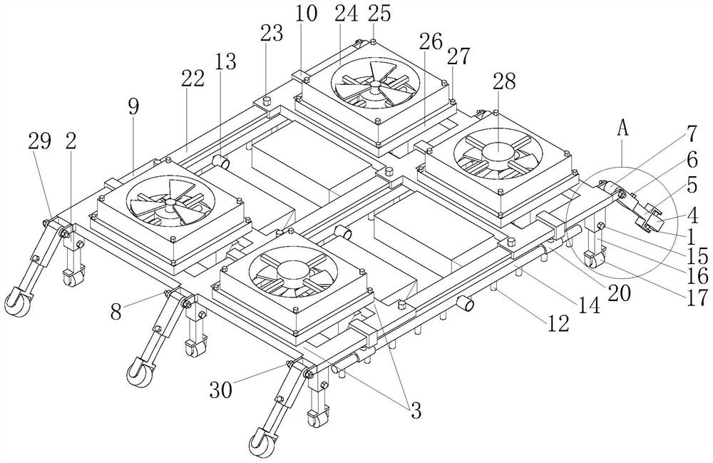
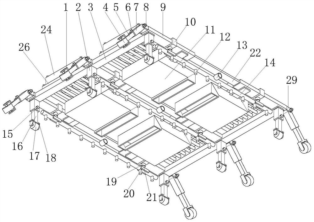
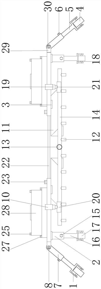
[0020] Such as Figure 1-4 As shown, a concrete maintenance device for water conservancy construction proposed by the present invention includes six symmetrical telescopic sleeves 9, telescopic rods 22 are slidably connected between the relative telescopic sleeves 9, and the telescopic sleeves 9 are threaded with bolts C23, bolts C23 Through the telescopic sleeve 9 and abut against the telescopic rod 22, a crossbar 3 is connected between the parallel telescopic sleeves 9, and the upper end of the crossbar 3 and the telescopic sleeve 9 is detachably connected with four evenly distributed heating devices 26, the heating device 26 The lower end communicates with an air duct 11, and the end of the air duct 11 away from the heating device 26 is set under the telescopic rod 22. The upper end of the heating device 26 can be detached with two sets of symmetrical exhaust fans 24 and intake fans 28, and the exhaust fans 24 and intake fans There are two fans 28 respectively and the posit...

no. 2 example

[0024] Such as Figure 1-4 As shown, the invention proposes a concrete maintenance device for water conservancy construction. Compared with the first embodiment, the sliding adjustment device A in this embodiment includes a sliding sleeve A2, a sliding rod A16, a bolt A15, a bracket A18 and a pulley A17 The upper end of the sliding sleeve A2 is connected to the telescopic sleeve 9, the sliding sleeve A2 is slidably connected to the slide bar A16, the slide bar A16 is connected to the support A18, the support A18 is rotated and connected to the pulley A17, and the sliding adjustment device A can adjust the height of the slide bar A16 according to the on-site ramp, ensuring The whole installation is level with the ramp of the hydraulic works.

no. 3 example

[0026] Such as Figure 1-4 As shown, a concrete maintenance device for water conservancy construction proposed by the present invention, compared with the first embodiment or the second embodiment, the side end of the telescopic sleeve 9 in this embodiment is connected with a fixed frame 29, and the fixed frame 29 rotates Connected with threaded rod 8, the two ends of threaded rod 8 all pass through fixing frame 29 and threaded connection nut 30, lock or loosen threaded rod 8 by nut 30, thereby guarantee the fixing and loosening of threaded rod 8.

[0027] The sliding adjustment device B includes a sliding sleeve B7, a sliding rod B5, a bolt B6, a bracket B1 and a pulley B4; the part of the threaded rod 8 between the fixed frames 29 is connected with the sliding sleeve B7, and the sliding sleeve B7 is slidably connected with the sliding rod B5, and the sliding rod B5 is connected with bracket B1, and bracket B1 rotates to connect with pulley B4. The sliding adjustment device B...


PUM


Abstract

The invention relates to the technical field of maintenance equipment, and in particular, relates to a concrete maintenance device for water conservancy construction, wherein the concrete maintenance device comprises six symmetrical telescopic sleeves, telescopic rods are slidably connected between the opposite telescopic sleeves, the telescopic sleeves are in threaded connection with bolts C, the bolts C penetrate through the telescopic sleeves and abut against the telescopic rods, and cross rods are connected between the parallel telescopic sleeves; four heating devices which are evenly distributed are detachably connected to the upper ends of the cross rods and the telescopic sleeves; the lower ends of the heating devices communicate with air pipes, the ends, away from the heating devices, of the air pipes are arranged below the telescopic rods, two sets of symmetrical exhaust fans and two symmetrical air inlet fans are detachably arranged at the upper ends of the heating devices, and the positions of the exhaust fans and the air inlet fans are symmetrical; and each telescopic sleeve is slidably connected with a sliding ring, a clamping ring is detachably connected to the lower portion of each sliding ring, each clamping ring is connected with a hard pipe in a clamped mode, the hard pipes are communicated with a plurality of evenly-distributed spray heads, and the hard pipes are communicated with connectors. Large-area water spraying humidification, temperature increasing, drying and dehumidification can be achieved, and the device can stably move on a ramp.

Description

technical field [0001] The invention relates to the technical field of maintenance equipment, in particular to a concrete maintenance device for water conservancy construction. Background technique [0002] After concrete is poured and tamped, the reason why it can gradually set and harden is mainly due to the result of cement hydration, and hydration requires appropriate temperature and humidity conditions. Therefore, in order to ensure that the concrete has suitable hardening conditions, its strength will continue to increase. , Concrete must be maintained, and most of the cement pavements that use concrete are sprinkled with water for natural maintenance, sprayed film maintenance, and plastic film wrapping maintenance. [0003] Water conservancy projects generally pour concrete in a large area. After the concrete is poured, if the climate is hot and the air is dry, if the maintenance is not carried out in time, the water in the concrete will evaporate too fast, forming a ...

Claims


Application Information

Patent Timeline
Patent Type & Authority Applications(China)
IPC IPC(8): C04B40/02E02B3/12
CPCC04B40/0281E02B3/121C04B40/0263
Inventor 陈秋兰陈丽林磊高慧敏
Owner 福建省京舜建设工程有限公司
Why Eureka
Try Eureka