
Cutting equipment for metallurgical machinery

A technology of cutting equipment and machinery, which is applied in the direction of metal processing equipment, shearing equipment, shearing devices, etc., can solve problems affecting work efficiency and processing accuracy, cutting point offset, and metallurgical materials cannot be fixed according to size, etc., to achieve Improve practicality and improve work efficiency

Pending Publication Date: 2021-12-31
惠州市靖睿自动化机械有限公司
View PDF6 Cites 0 Cited by
  • Summary
  • Abstract
  • Description
  • Claims
  • Application Information

AI Technical Summary

Problems solved by technology

[0002] Metallurgy refers to the process and technology of extracting metals or metal compounds from minerals, and using various processing methods to make metals into metal materials with certain properties. above the melting point) for slagging and slag removal to eliminate, and at the same time, certain chemical components can obtain relatively pure alloy components through slag removal, decarburization, deoxidation, etc. At present, in metallurgical processing, most of the cutting equipment The fixing fixtures are all fixed, so that the metallurgical material cannot be fixed according to the size during cutting, and the cutting point may shift during cutting, which affects work efficiency and processing accuracy

Method used


Image

  • Cutting equipment for metallurgical machinery
  • Cutting equipment for metallurgical machinery
  • Cutting equipment for metallurgical machinery

Examples


Embodiment Construction

[0025] In order to make the purpose, technical solution and advantages of the present invention clearer, the technical solution of the present invention will be clearly and completely described below in conjunction with specific embodiments of the present invention and corresponding drawings. Apparently, the described embodiments are only some of the embodiments of the present invention, but not all of them. Based on the embodiments of the present invention, all other embodiments obtained by persons of ordinary skill in the art without making creative efforts belong to the protection scope of the present invention.

[0026] The technical solutions provided by various embodiments of the present invention will be described in detail below in conjunction with the accompanying drawings.

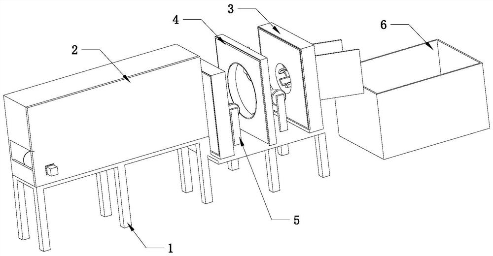
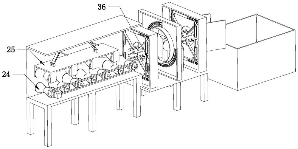
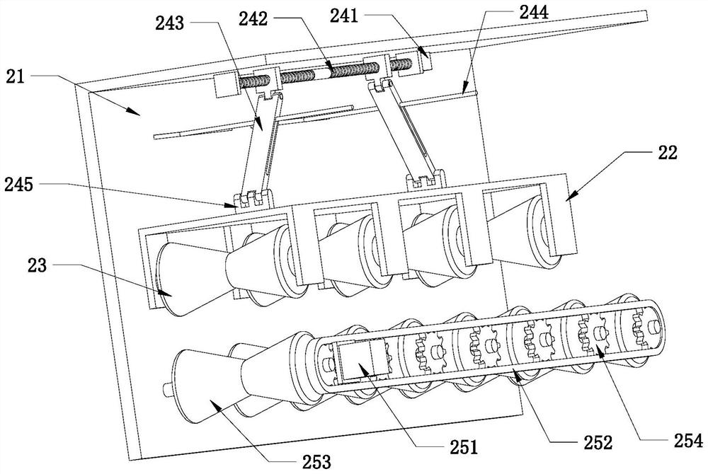
[0027] refer to Figure 1-Figure 8, the embodiment of the present invention provides a cutting device for metallurgical machinery, including a workbench 1, a traction mechanism 2, a clamping mec...


PUM


Abstract

The invention discloses cutting equipment for metallurgical machinery, and belongs to the technical field of metallurgical machinery. The cutting equipment comprises a workbench, a traction mechanism, two clamping mechanisms, a cutting mechanism, a supporting rolling shaft and a material collecting barrel. The traction mechanism is arranged at one end of the workbench, the two clamping mechanisms are symmetrically arranged on one side of the traction mechanism, the bottoms of the two clamping mechanisms are connected with the workbench, and a feeding port of one clamping mechanism corresponds to a discharging port of the traction mechanism; and the cutting mechanism is located between the two clamping mechanisms, the cutting mechanism and the two clamping mechanisms are arranged side by side, the bottom of the cutting mechanism is connected with the workbench, and the material collecting barrel is arranged at the other end of the workbench. The problems that in the prior art, fixing clamps on most of cutting equipment are fixedly arranged, metallurgical materials cannot be fixed according to the size during cutting, cutting points may deviate during cutting, and the working efficiency and the machining precision are influenced are solved.

Description

technical field [0001] The invention relates to the technical field of metallurgical machinery, in particular to a cutting device for metallurgical machinery. Background technique [0002] Metallurgy refers to the process and technology of extracting metals or metal compounds from minerals, and using various processing methods to make metals into metal materials with certain properties. above the melting point) for slagging and slag removal to eliminate, and at the same time, certain chemical components can obtain relatively pure alloy components through slag removal, decarburization, deoxidation, etc. At present, in metallurgical processing, most of the cutting equipment The fixing fixtures are all fixed, so that the metallurgical material cannot be fixed according to the size during cutting, and the cutting point may shift during cutting, which affects work efficiency and processing accuracy. When the invention cuts the metallurgical material, the clamps can be adjusted a...

Claims


Application Information

Patent Timeline
Patent Type & Authority Applications(China)
IPC IPC(8): B23D19/00B23D33/02
CPCB23D19/00B23D33/02
Inventor 卢进军王华忠肖康付
Owner 惠州市靖睿自动化机械有限公司
Learn More