Guardrail punching machine

A punching machine and guardrail technology, applied in the field of stamping equipment, can solve problems such as poor convenience of guardrails, and achieve the effects of improving convenience, reducing pulling strength, and improving stability

Pending Publication Date: 2021-12-31
陕西雄峰实业集团有限公司
View PDF12 Cites 3 Cited by
  • Summary
  • Abstract
  • Description
  • Claims
  • Application Information

AI Technical Summary

Problems solved by technology

[0004] In view of the above-mentioned related technologies, the inventor believes that using the guardrail punching machine in the related art needs to punch through holes of different diameters on the guardrail, and when punching through holes of different diameters, it is necessary to replace the punching tool installed on the heavy head. Less convenience for punching through holes of different diameters

Method used


Image

  • Guardrail punching machine
  • Guardrail punching machine
  • Guardrail punching machine

Examples


Embodiment Construction

[0033] Contraction below Figure 1-5 Further detailed description of the present application.

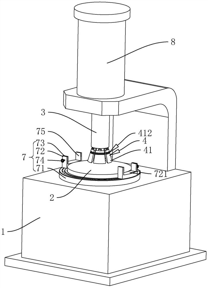
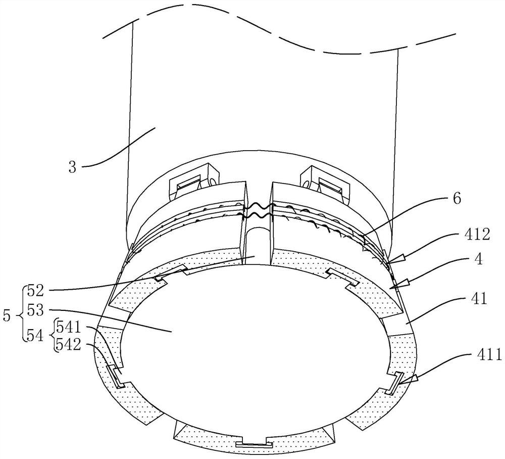
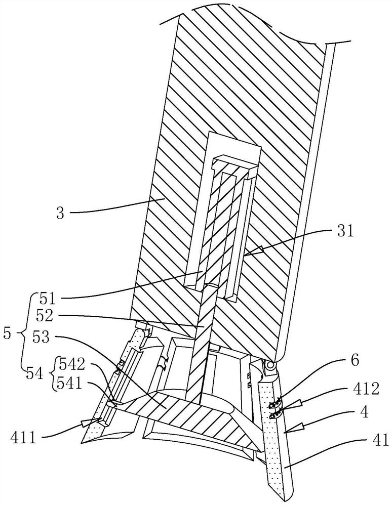
[0034] Example punch discloses a guardrail of the present application. Refer figure 1 , figure 2 and image 3 Guardrail punching machine comprises a frame 1, two pressure units, three punch, punch driving assembly 5 and the ring 4, the frame 1 is provided vertically, a cylindrical pressure stage 2, stage 2 vertically disposed pressure , pressure stage 2 and the frame 1 are integrally formed, punch 3 positioned above the frame 1, the frame 3 and the punch 1 sliding connection, 3 is also cylindrical punch, punch station 3 and the bearing 2 arranged coaxially, pressure punch 3 positioned at the top table 2, is provided with a punch press cylinder 8, the vertical press cylinder 8 is provided between the chassis 1 and 3, the press and the frame 8 of the cylinder housing 1 by means of bolted connections, stamping cylinder 8 and a ram piston rod 3 integrally formed; punching punch knife ring 4 p...


PUM


Abstract

The invention discloses a guardrail punching machine, and relates to the field of punching equipment. The guardrail punching machine comprises a rack, a pressure-bearing table and a punching head, the pressure-bearing table is connected with the rack, the punching head is slidably connected with the rack, the punching head is located at the top of the pressure-bearing table, the guardrail punching machine further comprises a punching ring and a driving assembly, the punching ring is arranged at the end, close to the pressure-bearing table, of the punching head, the punching ring comprises a plurality of punching cutters, and the multiple punching cutters are all hinged to the punching head. The driving assembly comprises driving blocks and guiding pieces, the driving blocks are located on the inner walls of the punching cutters and can move towards the side close to the punching head, the guiding pieces are located at the sides, facing the punching cutters, of the driving blocks, driving grooves are formed in the punching cutters, the driving grooves are formed in the moving direction of the driving blocks, the guiding pieces can slide along the driving grooves and can drive the punching cutters to move towards the sides away from each other or close to each other. According to the machine, the convenience of punching through holes with different diameters in a guardrail can be improved.

Description

Technical field [0001] The present application relates to the art of stamping devices, particularly to a guardrail punch. Background technique [0002] The opening of the building need to set the course of construction fence, the fence is set at the opening of the building can improve the safety of personnel, construction workers reduce the likelihood of the occurrence of falls, it is necessary to punch the guard rail fence in the manufacturing process of each species prepared hole, prepared hole punching process requires the use of guardrail punching machine. [0003] In the related art, the authorized announcement No. CN210907657U Chinese utility model patent discloses a fence with automatic punching machine for punching one kind of function, which includes a frame disposed vertically, the upper end of the frame with a vertical slip punch provided, the upper end of the frame is also provided with a drive assembly capable of driving the punch downwardly slip, corresponding to th...

Claims


Application Information

Patent Timeline
Patent Type & Authority Applications(China)
IPC IPC(8): B21D28/34B21D28/32B21D37/04
CPCB21D28/34B21D28/32B21D37/04
Inventor 刘丽恒雷小坤李群亚
Owner 陕西雄峰实业集团有限公司
Why Eureka
Try Eureka