
Organic electroluminescent device

An electroluminescence device and electroluminescence technology, which are applied in the direction of electro-solid devices, electrical components, semiconductor devices, etc., and can solve problems such as inability to determine the effect.

Pending Publication Date: 2021-12-28
JIANGSU SUNERA TECH CO LTD
View PDF9 Cites 0 Cited by
  • Summary
  • Abstract
  • Description
  • Claims
  • Application Information

AI Technical Summary

Problems solved by technology

However, in this publication, it is used as a capping layer, and its disclosed technical effect is only used as a capping layer material, and the effect of forming an electron transport layer with a lithium complex cannot be determined.

Method used


Image

  • Organic electroluminescent device
  • Organic electroluminescent device
  • Organic electroluminescent device

Examples


Embodiment 1

[0068] Embodiment 1: the synthesis of intermediate A2

[0069]

[0070] (1) In a 250mL three-necked flask, nitrogen gas was introduced, 0.02mol of 2-bromonaphthalene was added and dissolved in 100ml of tetrahydrofuran (THF), and then 0.024mol of bis(pinacol radical)diboron, 0.0002mol(1,1 ’ - bis(diphenylphosphine) ferrocene) dichloropalladium (II) and 0.05mol potassium acetate are added, the mixture is stirred, and the mixed solution of the above-mentioned reactants is heated to reflux for 5 hours; after the reaction is completed, cool and add 100ml of water, And the mixture was filtered and dried in a vacuum oven. The obtained residue was separated and purified through a silica gel column to obtain 4-biphenylboronic acid pinacol ester; the HPLC purity was 99.4%, and the yield was 90.7%. Elemental analysis structure (molecular formula C 16 h 19 BO 2 ): theoretical value C, 75.62; H, 7.54; B, 4.25; O, 12.59; test value: C, 75.65; H, 7.55; B, 4.27; MS (m / z): The theoreti...

Embodiment 2

[0078] Embodiment 2: the synthesis of compound 1:

[0079]

[0080] In a 250mL three-necked flask, blow nitrogen, add 0.01mol A1, 100ml DMF, 0.03mol B1, 0.0002mol palladium acetate, stir, and then add 0.02mol K 3 PO 4 Aqueous solution, heated to reflux reaction for 24 hours, sampling plate, the reaction is complete. Cool naturally, extract with 200ml of dichloromethane, separate layers, dry the extract with anhydrous sodium sulfate, filter, rotate the filtrate, and purify through a silica gel column to obtain the target product with a HPLC purity of 99.4% and a yield of 64.7%.

[0081] Elemental analysis structure (molecular formula C37H23N3O2): theoretical value C, 82.05; H, 4.28; N, 7.76; O, 5.91; test value: C, 82.06; H, 4.25; N, 7.80; O, 5.89. MS (m / z): theoretical value 541.18, found value 541.22.

Embodiment 3

[0082] Example 3: Synthesis of Compound 4: The difference between the synthesis of Compound 4 and the synthesis of Compound 1 is that A1 is replaced by A2, and the others remain unchanged to obtain the target product with a HPLC purity of 99.1% and a yield of 65.2%. Elemental analysis structure (molecular formula C41H25N3O2): theoretical value C, 83.23; H, 4.26; N, 7.10; O, 5.41; test value: C, 83.25; H, 4.27; N, 7.08; O, 5.40. MS (m / z): The theoretical value is 591.67, and the measured value is 591.69.


PUM

PropertyMeasurementUnit
Glass transition temperatureaaaaaaaaaa
Electron mobilityaaaaaaaaaa

Abstract

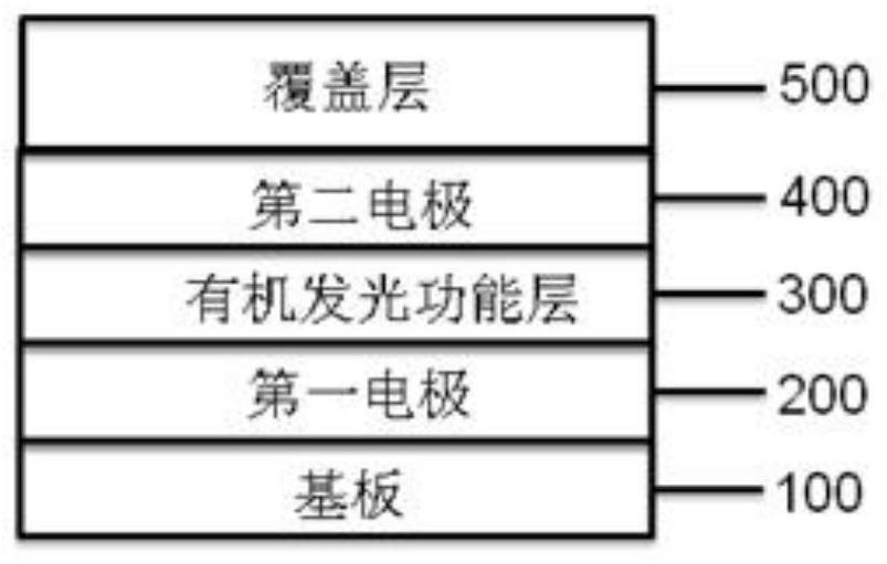
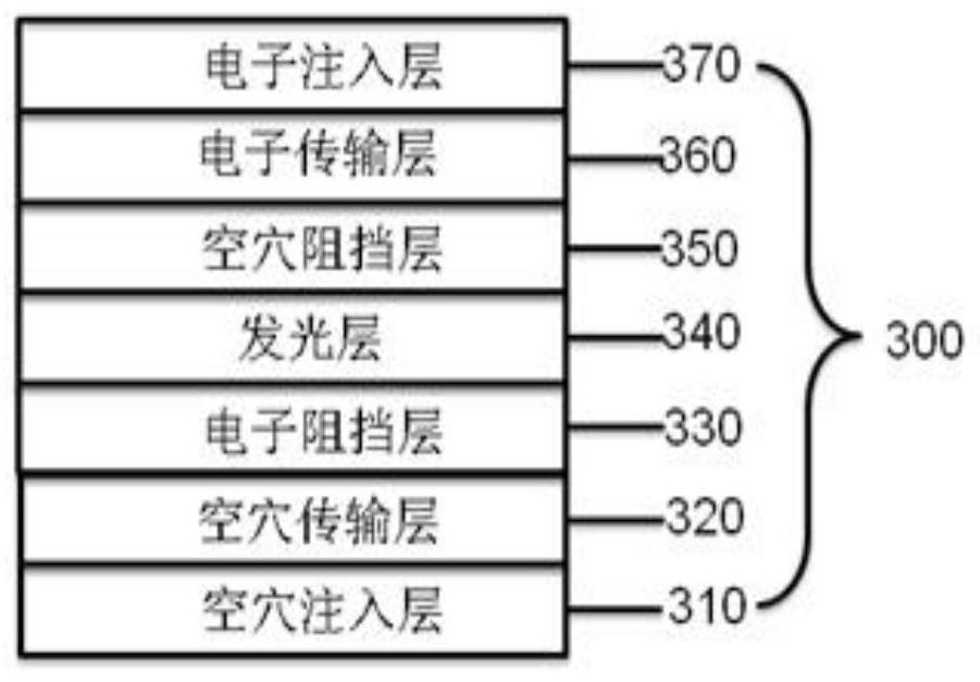
The present invention relates to an organic electroluminescent device. The organic electroluminescent device comprises a substrate layer; a first electrode which is arranged on the substrate; an organic light emitting functional layer on the first electrode; a second electrode arranged on the organic light-emitting functional layer; a capping layer over the second electrode, wherein the organic light emitting functional layer comprises an electron transport layer, the electron transport layer contains a first organic compound and a second organic compound, the first compound is selected from one of a general formula H1 and a general formula H2, and the second organic compound is selected from one of a general formula D1 and a general formula D2. The device structure provided by the invention can effectively improve the film phase state stability and heat-resistant stability of the electron transport layer and improve the electron injection and transport capabilities of the electron transport layer, thereby effectively reducing the driving voltage of the device, improving the luminous efficiency of the device and prolonging the service life of the device.

Description

technical field [0001] The invention relates to the technical field of organic electroluminescent materials, in particular to the application of an electron transport layer collocated on an organic electroluminescent device. Background technique [0002] Organic electroluminescent (OLED: Organic Light Emission Diodes) device technology can be used to manufacture new display products and also can be used to make new lighting products. It is expected to replace the existing liquid crystal display and fluorescent lighting, and has a wide application prospect. The OLED light-emitting device is like a sandwich structure, including electrode material film layers and organic functional materials sandwiched between different electrode film layers. Various functional materials are superimposed on each other according to the application to form an OLED light-emitting device. OLED light-emitting devices are current devices. When a voltage is applied to the electrodes at both ends, and ...

Claims


Application Information

Patent Timeline
IPC IPC(8): H01L51/50H01L51/54
CPCH10K85/624H10K85/622H10K85/615H10K85/631H10K85/636H10K85/633H10K85/654H10K85/657H10K85/6574H10K85/30H10K85/6572H10K50/16
Inventor 叶中华梁丽张兆超李崇
Owner JIANGSU SUNERA TECH CO LTD
Learn More