
Automatic point taking device of resiliometer

A technology of automatic point picking and rebound tester, which is applied to measuring devices, instruments, scientific instruments, etc., can solve the problems of potential safety hazards, aggravated safety hazards, and application of reaction force, etc., so as to save working space, optimize structure, and reduce equipment cost effect

Pending Publication Date: 2021-12-24
武汉市中心工程检测有限公司
View PDF10 Cites 0 Cited by
  • Summary
  • Abstract
  • Description
  • Claims
  • Application Information

AI Technical Summary

Problems solved by technology

[0004] However, when engineering personnel measure the concrete compressive strength of load-bearing beams in the construction site building, since the load-bearing beams are all located at high altitudes, the work is difficult and there are potential safety hazards. The special spring will exert a reaction force on the construction personnel and directly act on the ladder, which will aggravate the safety hazard

Method used


Image

  • Automatic point taking device of resiliometer
  • Automatic point taking device of resiliometer
  • Automatic point taking device of resiliometer

Examples


Embodiment 1

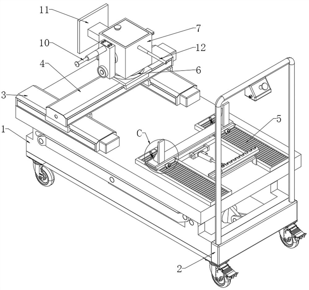
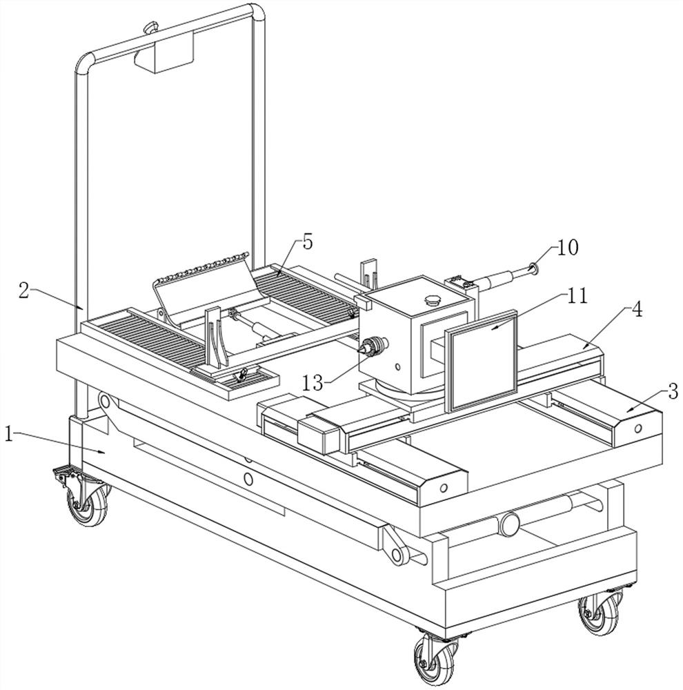
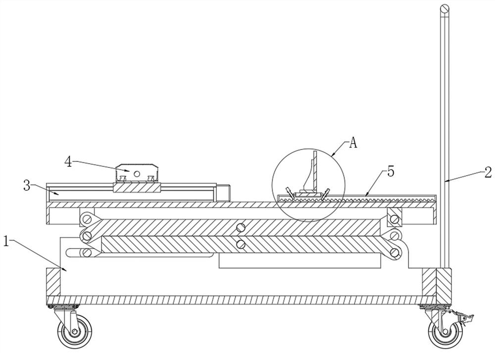
[0038] see Figure 1-10, an automatic point-taking device for a rebound hammer, comprising a lifting trolley 1, a push rod 2 is arranged on one side of the lifting trolley 1, and a longitudinal electric slide rail 3 and a crossbeam clamping device 5 are arranged on the top of the lifting trolley 1, The top of the longitudinal electric slide rail 3 is provided with a horizontal electric slide rail 4, and the top of the horizontal electric slide rail 4 is provided with an electric turntable 6, and the top of the electric turntable 6 is rotatably connected with a turntable 7, and the four sides of the turntable 7 are respectively provided with springback Instrument 10, square stamp 11, catheter 12, drill bit clamp 13, distance measuring camera 21.

[0039] refer to Figure 5 , the top of the turntable 7 is fixedly connected with a drill clamp 13, one side of the drill clamp 13 is provided with a peristaltic pump 14, the input end of the peristaltic pump 14 communicates with the ...

Embodiment 2

[0047] Please refer to Figure 10 , this embodiment is compared with embodiment 1, the difference is that: the rebound instrument 10 and the square stamp 11 are arranged on the outer wall of the turntable 7 oppositely, and the bevel gear three 906, the gear set two 907, and the one-way bearing 903 , transmission shaft 904, correspondingly changing its transmission position.

[0048] Compared with the rebound hammer 10 and the square seal 11 being adjacently arranged on the outer wall of the turntable 7, the rebound hammer 10 and the square seal 11 are arranged opposite to each other, so that the size of the square seal 11 can be unlimited, thereby reducing the number of imprints and improving the purpose of work efficiency.

[0049] see Figure 8 Compared with Embodiment 1, this embodiment differs in that: the transmission end of the driving device 2 or the driving device 2 6 is in transmission connection with the transmission connection head 2 405 of the steering transmissi...


PUM


Abstract

The invention discloses an automatic point taking device for a resiliometer, and belongs to the field of quality detection. The automatic point taking device comprises a lifting cart, a push rod is arranged at one side of the lifting cart, a longitudinal electric sliding rail and a cross beam clamping device are arranged at the top of the lifting cart, a transverse electric sliding rail is arranged at the top of the longitudinal electric sliding rail, an electric rotating disc is arranged at the top of the transverse electric sliding rail, a rotating table is rotationally connected to the top of the electric rotating disc, the resiliometer, a square seal, a guide pipe, a drill bit clamp and a distance measuring camera are arranged on the four faces of the rotating table correspondingly, the drill bit clamp is fixedly connected to the top of the rotating table, and a peristaltic pump is arranged at one side of the drill bit clamp; the input end of the peristaltic pump is communicated with the drill bit clamp, the output end of the peristaltic pump is communicated with a liquid conveying pipe, the liquid conveying pipe penetrates through the rotating table and is inserted into the guide pipe, efficient automatic point taking of the resiliometer can be achieved, concrete carbonization can be detected, and meanwhile, the device has a simpler and more convenient structure.

Description

technical field [0001] The invention relates to the field of quality inspection, and more specifically relates to an automatic point-taking device for a rebound hammer. Background technique [0002] The basic principle of the rebound tester is to use a spring to drive the heavy hammer, and the heavy hammer hits the bullet rod in vertical contact with the concrete surface with constant kinetic energy, so that the local concrete deforms and absorbs part of the energy, and the other part of the energy is converted into the rebound kinetic energy of the heavy hammer , when all the kinetic energy of the rebound is converted into potential energy, the weight rebounds to the maximum distance, and the instrument displays the maximum rebound distance of the weight in the name of the rebound value. [0003] In order to measure the strength value of concrete, it is the maximum stress that concrete can bear under a certain stress state and working conditions. In order to accurately meas...

Claims


Application Information

Patent Timeline
IPC IPC(8): F16M11/04F16M11/10F16M11/18F16M11/38F16M11/42F16M13/02G01N3/52G01N3/04G01N3/02
CPCF16M11/045F16M11/048F16M11/10F16M11/18F16M11/38F16M11/42F16M13/022G01N3/52G01N3/04G01N3/02G01N2203/0035G01N2203/0039G01N2203/0083G01N2203/0641Y02P70/10
Inventor 周志伟胡安王勇戚威张永年曹明旺李晶阳张迪刘绍鑫严欣程
Owner 武汉市中心工程检测有限公司
Learn More