
Mine underground water dynamic monitoring system, control method and application

A dynamic monitoring and groundwater technology, applied in the direction of measurement, mining equipment, mining equipment, etc., can solve the problems of low efficiency, long demonstration period, difficult identification, etc., and achieve the effect of perfecting the comprehensive management system

Pending Publication Date: 2021-12-21
四川省煤炭设计研究院 +1
View PDF0 Cites 3 Cited by
  • Summary
  • Abstract
  • Description
  • Claims
  • Application Information

AI Technical Summary

Problems solved by technology

[0004] (1) The existing conventional water source identification methods have problems such as long demonstration period and low efficiency, and are easily interfered by human factors
[0005] (2) Although the underground water tank is equipped with a water level sensor, it can only determine whether the underground water gushing has increased, and cannot accurately determine the exact location of the change in the water source and the change in the water quality
[0008] Some aquifers have obvious chemical characteristics, but some aquifers have similar hydrochemical characteristics, and it is difficult to accurately identify them by relying on a single factor, and traditional identification methods have great limitations;

Method used


Image

  • Mine underground water dynamic monitoring system, control method and application
  • Mine underground water dynamic monitoring system, control method and application
  • Mine underground water dynamic monitoring system, control method and application

Examples


Embodiment Construction

[0041] In order to make the object, technical solution and advantages of the present invention more clear, the present invention will be further described in detail below in conjunction with the examples. It should be understood that the specific embodiments described here are only used to explain the present invention, not to limit the present invention.

[0042] Aiming at the problems existing in the prior art, the present invention provides a mine groundwater dynamic monitoring system, control method and application. The present invention will be described in detail below in conjunction with the accompanying drawings.

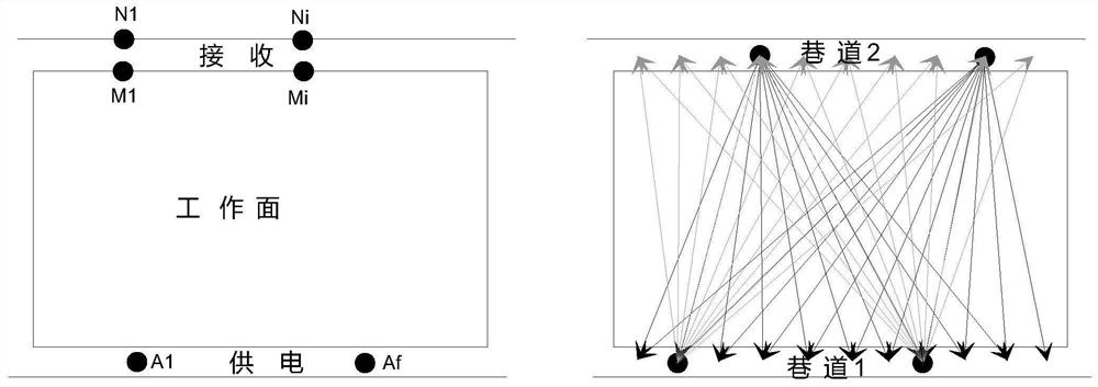
[0043] Combined with the actual situation of the coal mine, set up 1 ground monitoring center, 1 ground rainfall monitoring station, 1 ground long observation hole monitoring station, and 4 underground monitoring stations (increase or decrease according to the number of mine layouts)

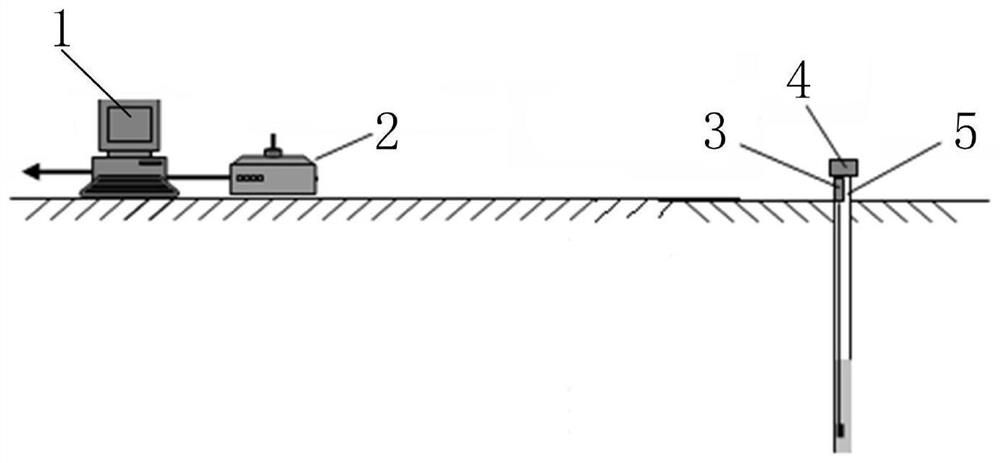
[0044] Such as figure 1 As shown, in the mine groundwater dynamic monito...


PUM


Abstract

The invention belongs to the technical field of hydrological monitoring, and discloses a mine underground water dynamic monitoring system, a control method and application. A monitoring computer is connected to an intelligent water level remote sensing instrument through a remote communication adapter, and the intelligent water level remote sensing instrument is installed in a field hydrological observation hole. According to the mine underground water dynamic monitoring system, the control method and the application, through research and application of a comprehensive mine water disaster prevention and control technology, a mine water chemical laboratory and an automatic real-time monitoring system for water conditions above and below the mine are established, a rapid water inrush source judgment system and a prevention and control key technology system suitable for mine area water disaster characteristics are formed, mine water inrush prediction and early warning are carried out in time, the method has important guiding significance on mine water prevention and control work, safe production and construction of a mine are guaranteed, a reference function is provided for the surrounding mine water prevention and control work with similar hydrogeological conditions, coal mine water inrush risk evaluation and control technology system construction are completed, a mine water source rapid judgment and mine underground water dynamic monitoring system and emergency mechanism linkage system is formed, and a mining area water prevention and control comprehensive management system is perfected.

Description

technical field [0001] The invention belongs to the technical field of hydrological monitoring, in particular to a mine groundwater dynamic monitoring system, control method and application. Background technique [0002] At present, mine water damage is a major hidden danger affecting mine safety production. In our country, almost all mines are facing different degrees of flooding. The most important basis for flood prevention and control is to determine the water source of the effluent, so as to take reasonable prevention and control measures and countermeasures. There are currently two main methods for identifying mine water sources: one is the water quality analysis method, which collects water samples for water quality testing and compares water chemical indicators to determine the water source; Turbidity, smell, taste, water temperature, water pressure and other characteristics, and judge the water source through experience. For the prevention and control of mine wat...

Claims


Application Information

Patent Timeline
Patent Type & Authority Applications(China)
IPC IPC(8): E21F17/18E21B47/00E21B47/047E21B47/06E21B47/07
CPCE21F17/18E21B47/00E21B47/047E21B47/06E21B47/07
Inventor 王海军赵清全付康国李胜江曹运飞叶飞杨庆朝郑万成刘超
Owner 四川省煤炭设计研究院
Learn More