
A method for installing a counterforce frame

An installation method and a technology of a reaction frame, which are applied in the direction of earthwork drilling, mining equipment, tunnels, etc., can solve problems such as uneven stress on negative ring segments, inability to use shield tunnels for safe production and construction, and cracks, etc. Uniform force, ensuring the safe production and construction of shield tunneling, and ensuring the effect of normal use

Active Publication Date: 2020-06-16
广东欣龙隧道装备股份有限公司
View PDF14 Cites 0 Cited by
  • Summary
  • Abstract
  • Description
  • Claims
  • Application Information

AI Technical Summary

Problems solved by technology

[0003] The traditional installation method of the reaction force frame is difficult to ensure that the contact surface between the reaction force frame and the negative ring segments is close and dense. The elastic and non-elastic deformation of the reaction force frame under the force causes a gap between the force surface of the negative ring segment and the contact surface of the reaction force frame, resulting in uneven stress, cracks, damage, or even failure of the negative ring segment. Normal use and guarantee safe production and construction of shield tunneling

Method used


Image

  • A method for installing a counterforce frame
  • A method for installing a counterforce frame
  • A method for installing a counterforce frame

Examples


Embodiment Construction

[0029] This part will describe the specific embodiment of the present invention in detail, and the preferred embodiment of the present invention is shown in the accompanying drawings. Each technical feature and overall technical solution of the invention, but it should not be understood as a limitation on the protection scope of the present invention.

[0030] In the description of the present invention, it should be understood that the orientation descriptions, such as up, down, front, back, left, right, etc. indicated orientations or positional relationships are based on the orientations or positional relationships shown in the drawings, and are only In order to facilitate the description of the present invention and simplify the description, it does not indicate or imply that the device or element referred to must have a specific orientation, be constructed and operated in a specific orientation, and thus should not be construed as limiting the present invention.

[0031] I...


PUM


Abstract

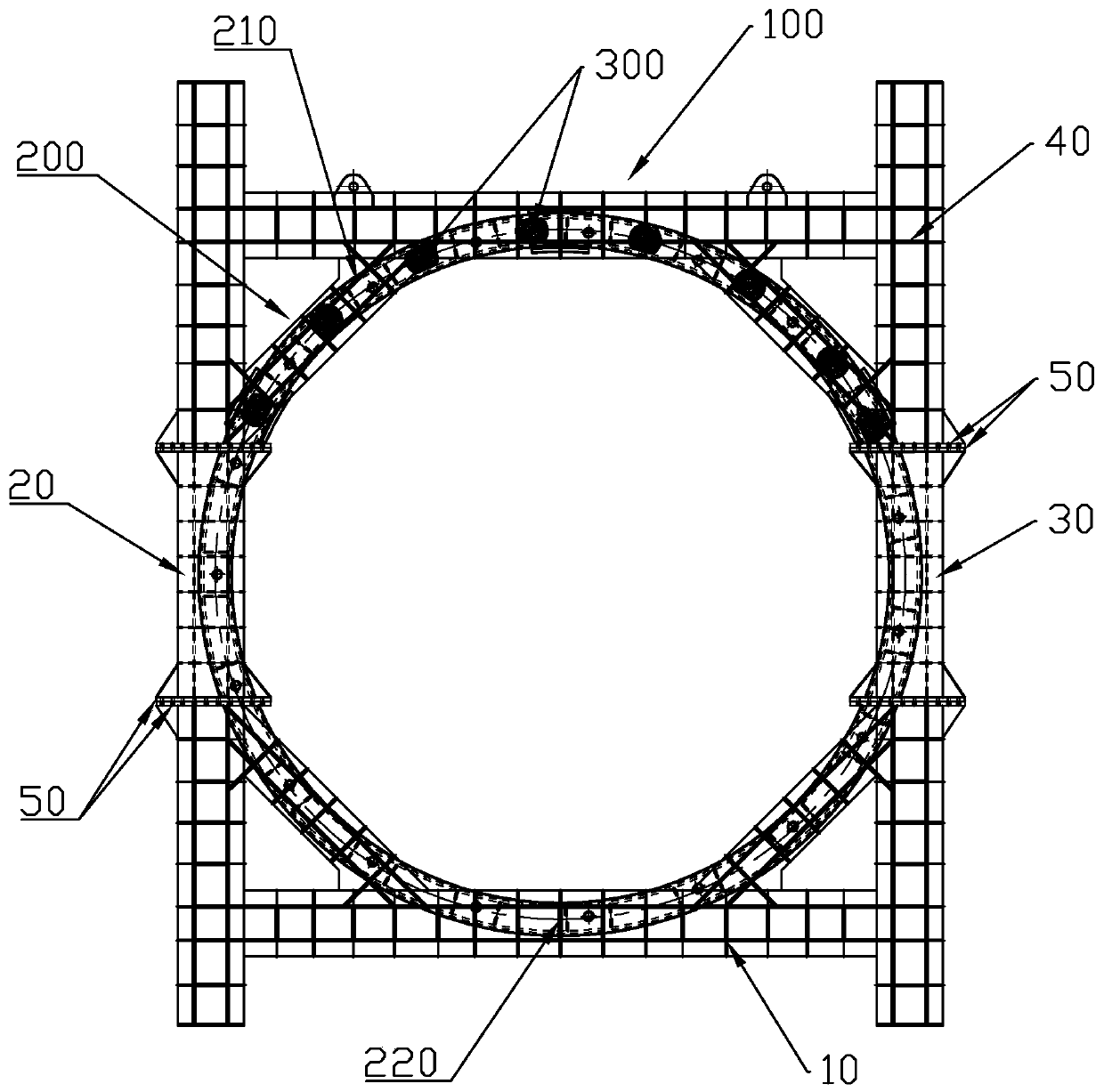
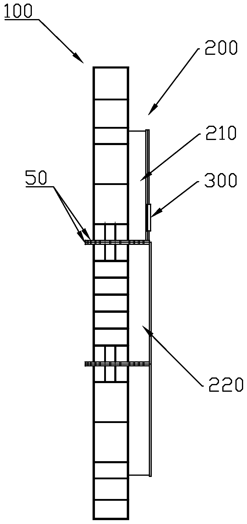
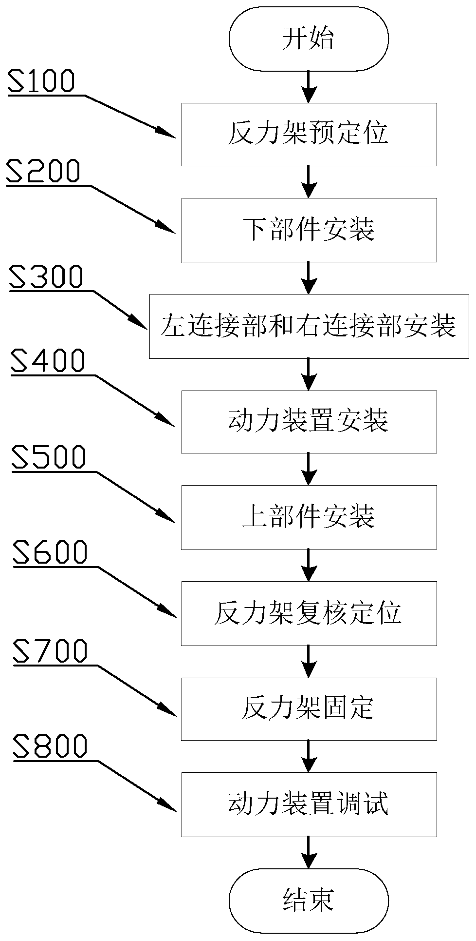
The invention discloses a counterforce frame mounting method, and relates to the technical field of building construction. The counterforce frame mounting method includes the following steps that a counterforce frame is pre-positioned, specifically, the site mounting position is measured according to a design scheme, and the mounting position of the counterforce frame is pre-positioned; the counterforce frame is mounted, specifically, a lower part, a left connecting part, a right connecting part and an upper part are sequentially mounted and fixed, and power devices are mounted on the corresponding position of a first annular section; the counterforce frame is subjected to re-check positioning, specifically, the front-rear position, the horizontal position and the vertical position of thecounterforce frame are rechecked and adjusted; the counterforce frame is fixed, specifically, the lower part and a steel plate base are welded and fixed, and a supporting part is welded and fixed between the counterforce frame and the steel plate base; and the power devices are debugged, specifically, the extending and retraction length and pressure of each set of power device are adjusted to enable the power devices to abut against corresponding negative ring segments. Through the adjusting effect of the power devices arranged on the upper part, the negative ring segments bear force evenly, and normal use of the negative ring segments and shield safe production and construction are ensured.

Description

technical field [0001] The invention relates to the technical field of building construction, in particular to a method for installing a reaction force frame. Background technique [0002] The reaction frame is an important part of the starting of the shield machine. The initial propulsion of the shield machine transmits the thrust to the reaction frame through the negative ring segments. The reaction force is transmitted to the shield machine, so that the shield machine moves forward. [0003] The traditional installation method of the reaction force frame is difficult to ensure that the contact surface between the reaction force frame and the negative ring segments is close and dense. The elastic and non-elastic deformation of the reaction force frame under the force causes a gap between the force surface of the negative ring segment and the contact surface of the reaction force frame, resulting in uneven stress, cracks, damage, or even failure of the negative ring segmen...

Claims


Application Information

Patent Timeline
Patent Type & Authority Patents(China)
IPC IPC(8): E21D9/06E21D9/00
CPCE21D9/003E21D9/06
Inventor 陈国昌刘志斌陈美婷郑杨锐靳建伟陈晓曦
Owner 广东欣龙隧道装备股份有限公司
Learn More