
Hydraulic fracturing rock breaking method and system

A hydraulic fracturing and rock-breaking technology, applied in earth-moving drilling, discharging machinery, etc., can solve the problems of insufficient expansion effect, multiple safety risks, and error-prone, and achieve the effect of controllable crushing direction.

Pending Publication Date: 2021-12-21
YANTAI JEREH PETROLEUM EQUIP & TECH CO LTD
View PDF11 Cites 0 Cited by
  • Summary
  • Abstract
  • Description
  • Claims
  • Application Information

AI Technical Summary

Problems solved by technology

Commonly used physical blasting methods are carbon dioxide gas crushing, hydraulic splitting, expansion agent splitting, physical cutting, water jet cutting, etc., but the above physical crushing methods are all small volume crushing methods except carbon dioxide gas crushing. The disadvantages of low operating efficiency and generally high operating costs
As for the crushing of carbon dioxide gas, because its blasting mechanism relies on high temperature breakdown of the safety film to instantly gasify carbon dioxide and generate gas impact force to crush the ore, there are also more safety risks.
Moreover, due to the cumbersome operations such as filling, wiring, and hole sealing, which are prone to errors, the operating efficiency is not high; the expansion rock breaking technology can effectively control the blasting range, and the rock mass will be swollen and broken through the continuous expansion of the expansion agent. A large amount of expansion agent is required, the cost is high, and there is still a problem of disposal of the used expansion agent. Secondly, because the expansion agent is used to expand the rock, the deformation of the expansion agent is limited, and the expected expansion effect is often not achieved. The reaction generally takes several hours, and the efficiency is low
Similarly, the use of hydraulic splitters also has problems such as low efficiency and serious equipment wear. When it is necessary to control the direction of rock mass rupture under special circumstances, the limitations of explosive blasting technology are more prominent.

Method used


Image

  • Hydraulic fracturing rock breaking method and system
  • Hydraulic fracturing rock breaking method and system
  • Hydraulic fracturing rock breaking method and system

Examples


Embodiment Construction

[0028] The principles and features of the present invention are described below in conjunction with the accompanying drawings, and the examples given are only used to explain the present invention, and are not intended to limit the scope of the present invention.

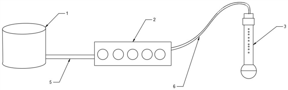
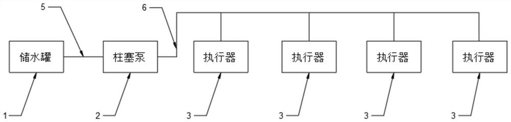
[0029] Please refer to figure 1 As shown, a hydraulic fracturing system includes a water storage tank 1, a plunger pump 2 and an actuator 3. The water storage tank 1 is used to store water, and the water storage tank 1 and the plunger pump 2 are connected by a low-pressure water pipe. 5 connection, the plunger pump 2 and the actuator 3 are connected through a high-pressure water pipe 6, and the plunger pump 2 is used to pressurize water to obtain high-pressure water;

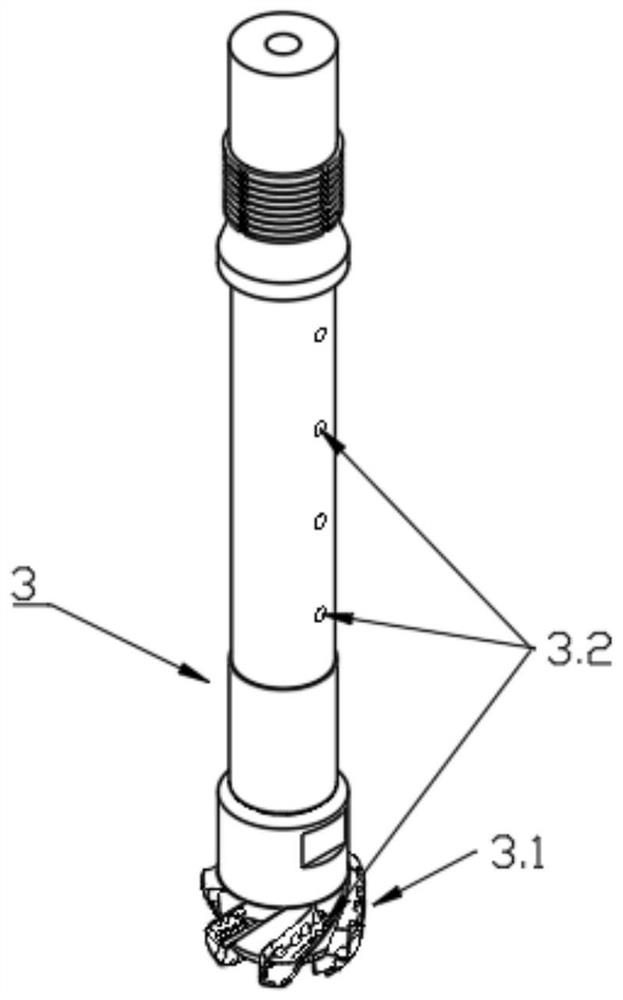
[0030] Such as figure 2 As shown, the head of the actuator 3 is a diamond drill bit 3.1, and the diamond drill bit 3.1 is used to open a hole 4 on the rock mass 7; the actuator 3 is internally provided with a water flow path communicating with the o...


PUM


Abstract

The invention discloses a hydraulic fracturing rock breaking method. The method comprises the steps that a plurality of holes are formed in the position requiring rock breaking in a mine in advance, a pressurizing device is used for pressurizing water to obtain high-pressure water, an outlet of the pressurizing device communicates with the interiors of the holes through a high-pressure pipe, a sealing device is arranged at the joint of the high-pressure pipe and the holes, the high-pressure water is injected into the holes, the water pressure of the high-pressure water is continuously increased until the pressure in the hole exceeds the highest crack extension pressure of the rock mass, and the rock mass is broken. Therefore, according to the hydraulic fracturing rock breaking method, dust and vibration are avoided in the rock breaking process, and environmental pollution is avoided. The invention further discloses a hydraulic fracturing rock breaking system.

Description

technical field [0001] The invention relates to the field of rock breaking in mines, in particular to a hydraulic fracturing rock breaking method and a hydraulic fracturing rock breaking system. Background technique [0002] In the process of rock mining in mines, rocks need to be crushed and stripped. At present, the commonly used method is to use explosive blasting. However, the blasting method has problems such as difficult to control the amount of charge, blind shots, etc., and there are vibrations, flying stones, etc. in the process. Safety and environmental protection issues such as dust and noise, and explosive blasting cannot control the direction of rock mass crushing. [0003] With the strengthening of control and use restrictions on blasting mining, the technology of rock breaking using physical methods is widely used. Commonly used physical blasting methods are carbon dioxide gas crushing, hydraulic splitting, expansion agent splitting, physical cutting, water j...

Claims


Application Information

Patent Timeline
Patent Type & Authority Applications(China)
IPC IPC(8): E21C37/12
CPCE21C37/12
Inventor 马金铭张兴鲁曲宇刘佳
Owner YANTAI JEREH PETROLEUM EQUIP & TECH CO LTD
Learn More