
Aircraft and control method

A control method and aircraft technology, which is applied in the field of aircraft, can solve the problems of poor comfort and complexity of the human body, achieve good comfort, reduce self-weight, and reduce the effects of mutual disturbance

Pending Publication Date: 2021-12-21
成都力跑科技有限公司
View PDF0 Cites 0 Cited by
  • Summary
  • Abstract
  • Description
  • Claims
  • Application Information

AI Technical Summary

Problems solved by technology

[0003] The purpose of the invention of the present invention is: for the single-person aircraft of the prior art, when adjusting the flight direction and speed of the aircraft by changing the collective pitch and the periodic pitch of the rotor, there are complex design of the structure, high requirements for parameter control and difficult flight. In order to solve the problem of poor comfort of the human body, an aircraft and a control method are provided, which can change the moving direction and flight speed of the aircraft, without complicated structural design to change the collective pitch and periodic pitch of the rotor, and reduce the requirements for parameter control , the aircraft changes the flight direction more smoothly, improving the comfort of the human body during flight

Method used


Image

  • Aircraft and control method
  • Aircraft and control method
  • Aircraft and control method

Examples


Embodiment 1

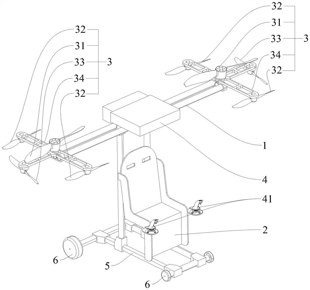
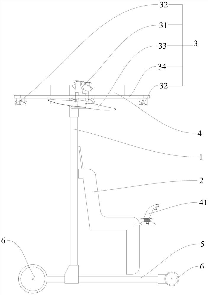
[0062] Such as Figure 1-Figure 2 As shown, a kind of aircraft of the present invention comprises flight frame 1, and flight frame 1 is fixed with carrier part 2, two groups of rotor assemblies 3 and control system 4, and carrier part 2 is positioned at the front of flight frame 1, and carrier part 2 is used for carrying People, the control system 4 is used to control the rotor assembly 3, and the two sets of rotor assemblies 3 are symmetrically located on the left and right sides of the flight frame 1 relative to the carrier part 2;

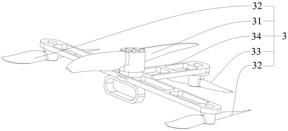
[0063] Every group of rotor assembly 3 comprises lift rotor 31 and attitude rotor one 32 and attitude rotor two 33, and lift rotor 31 is positively fixed on the flight frame 1, and the rotation axis of lift rotor 31 is inclined to the front of flight frame 1 and is arranged, and attitude rotor One 32 is reversely and vertically fixed on the flight frame 1, and a plurality of lift rotors 31 are arranged symmetrically, the attitude rotor two 33 is...

Embodiment 2

[0071] A kind of control method of aircraft, control a kind of aircraft as described in embodiment 1, the control method of the advancing, lifting or turning state of aircraft in the air is as follows respectively:

[0072] 1. The advance of the aircraft in the air includes constant speed advance, accelerated advance and decelerated advance. The control method of each state is as follows:

[0073] When it is necessary to advance at a constant speed, control the rotating speed of the lift rotor 31 to balance the horizontal force of the aircraft;

[0074] When needing to accelerate forward, increase the rotating speed of lift rotor 31 on the basis of advancing at a constant speed;

[0075] When it is necessary to slow down and move forward, start the two attitude rotors 2 33 synchronously to offset part of the horizontal power of the aircraft;

[0076] 2. The lift of the aircraft in the air includes constant speed lift, acceleration lift, deceleration lift and stop lift. The co...


PUM

PropertyMeasurementUnit
Diameteraaaaaaaaaa
Diameteraaaaaaaaaa
Lengthaaaaaaaaaa

Abstract

The invention relates to the technical field of aircrafts and discloses an aircraft and a control method. The aircraft comprises a flight frame, wherein a carrier component, two rotor wing assemblies and a control system are fixed to the flight frame, and the two rotor wing assemblies are symmetrically located on the left side and the right side of the flight frame relative to the carrier component; each group of rotor assemblies comprises a lift rotor, a plurality of attitude rotors I and a plurality of attitude rotors II, the lift rotors are positively fixed on the flight frame, rotating shafts of the lift rotors are obliquely arranged towards the front of the flight frame, the attitude rotors I are reversely and vertically fixed on the flight frame and are symmetrically arranged relative to the lift rotors, a attitude rotor 2 is fixed on the flight frame in reverse, and the rotation axis of the attitude rotor 2 is inclined towards the rear of the flight frame; according to the aircraft and the control method, through the cooperative design of the multiple rotors at different positions, the flight attitude of the aircraft is controlled through the rotating speed difference of the multiple rotors, the rotors work at the fixed screw pitch, and the complex structural design is avoided, and the requirement for parameter control is lowered.

Description

technical field [0001] The invention relates to the technical field of aircraft, in particular to an aircraft and a control method. Background technique [0002] At present, the single-person aircraft driven by the rotor is usually driven by the rotors located on both sides of the carrier in order to be able to fly flexibly in the air. The control system changes the collective pitch and the periodic pitch of the two rotors, and the swash plate mechanism is used. Control the flight attitude of the aircraft in the air, and then realize the change of the moving direction and speed state of the aircraft in the air. Due to the complicated design of the swash plate mechanism, the requirements for parameter control are high, which increases the difficulty of the control system, and when changing the flight attitude , the entire aircraft shakes violently, and the comfort of the human body is poor during flight. Contents of the invention [0003] The purpose of the invention of th...

Claims


Application Information

Patent Timeline
IPC IPC(8): B64C27/08B64C27/52B64C19/00G05D1/08G05D1/10
CPCB64C27/08B64C27/52B64C19/00G05D1/0808G05D1/106
Inventor 胡俊
Owner 成都力跑科技有限公司
Learn More