
Stirring device for cement-based composite shielding material

A composite shielding and stirring device technology, which is applied in the field of cement-based materials, can solve the problems of electromagnetic shielding materials that cannot be uniformly mixed, electromagnetic shielding materials fall wantonly, etc., and achieve the effect of improving the mixing effect

Pending Publication Date: 2021-12-21
徐州安高新型建材产业技术研究院有限公司
View PDF6 Cites 0 Cited by
  • Summary
  • Abstract
  • Description
  • Claims
  • Application Information

AI Technical Summary

Problems solved by technology

[0005] However, all electromagnetic shielding materials, whether it is carbon fiber, stainless steel fiber or graphite, are extremely small in size and light in weight before being mixed into the cement base. , which in turn leads to the fact that the electromagnetic shielding material in the formed crystal mud machine material cannot be uniformly mixed into the cement base, so this technical solution provides an improved cement-based mixing device that can evenly spread materials on the existing cement-based mixing device

Method used


Image

  • Stirring device for cement-based composite shielding material
  • Stirring device for cement-based composite shielding material
  • Stirring device for cement-based composite shielding material

Examples


Embodiment 1

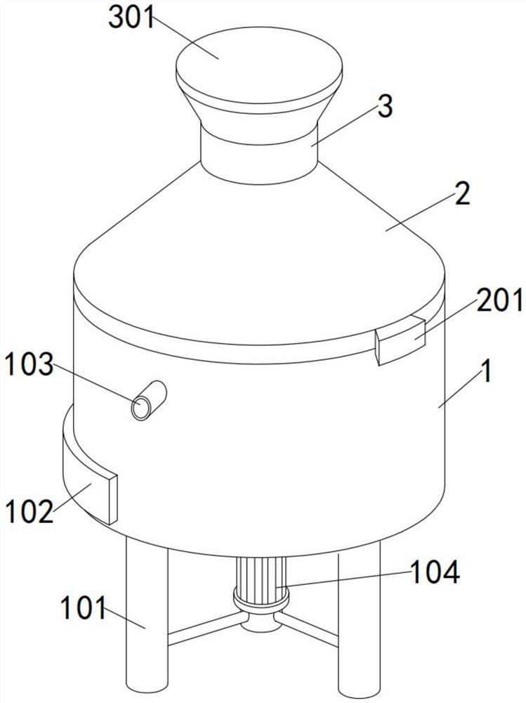
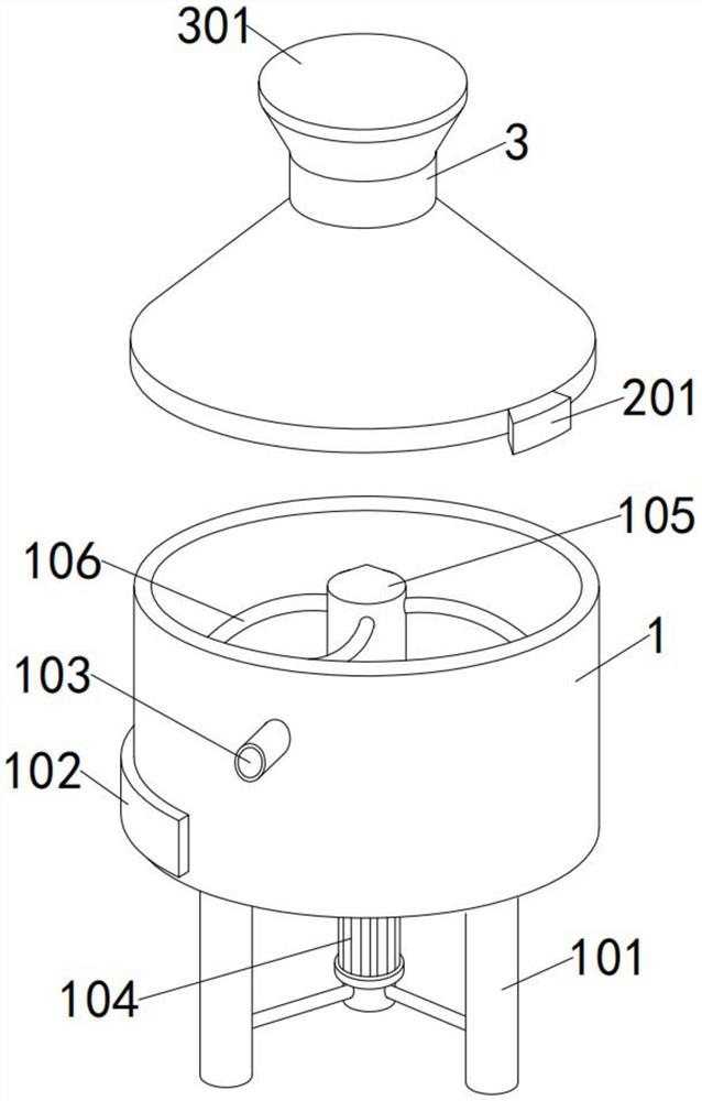
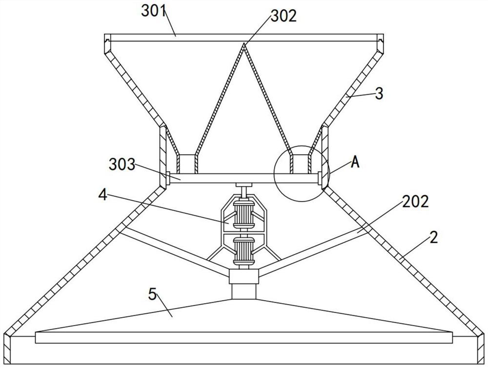
[0039] see Figure 1-6, in the embodiment of the present invention, a top cover 2 is installed above the mixing bucket 1, a leg 101 is fixedly connected to the bottom of the mixing bucket 1, a discharge plate 102 is movably connected to the bottom of the side of the mixing bucket 1, and an inlet is embedded in the side of the mixing bucket 1. The water pipe 103 is connected to the rotating shaft 105 inside the mixing tank 1, and the stirring rod 106 is fixed at an equal angle around the rotating shaft 105. The stirring motor 104 is fixedly connected to the leg 101, and the power output end of the stirring motor 104 passes through the bottom of the rotating shaft 105. The gears are connected by transmission, the top of the top cover 2 is fixedly connected with the batching hopper 3, and the diameter of the bottom of the top cover 2 is consistent with the diameter of the top of the top cover 2, and the top cover 2 is set in a trapezoidal shape, and the batching hopper 3 is set in...

Embodiment 2

[0043] see Figure 5 , Figure 7 and Figure 8 , in this embodiment, the top of the diversion turntable 5 is embedded with a central rod 501, the side of the diversion turntable 5 is provided with a frame 502, a support rod 504 is fixedly connected between the inner side of the frame 502 and the center rod 501, and the top of the support rod 504 is fixedly connected There is a panel 503, and there are four groups of panels 503, and the length of each group is divided into three sections with equal lengths. The upper surface of the panel 503 is fixedly connected with a deflector 505, and the deflector 505 is installed on the three-section panel in turn. of the segment.

[0044] In this embodiment, when the electromagnetic shielding material falls above the diversion turntable 5, that is, it falls above the panel 503, since the position where the electromagnetic shielding material falls through the tube 3031 is fixed, when the diversion turntable 5 rotates , the electromagnet...

Embodiment 3

[0046] see Figure 9-10 , in this embodiment, the top of the central rod 501 is fixedly connected with a sleeve 5011, and a screw hole is provided in the sleeve 5011 to facilitate the power transmission between the diversion turntable 5 and the driving mechanism 4, and the central rod 501 is hollow to The bottom is open, and the center rod 501 is connected with an exhaust fan 5012 in rotation. The bottom of the center rod 501 is nested with a bottom filter 5013, and the cross section of the bottom filter 5013 is an arc shape with the center protruding downward. The lower curved tube 5014 is embedded inside, and the lower curved tube 5014 is arranged above the panel 503, and the lower curved tube 5014 is in the shape of an L bent downward as a whole, and the end of the lower curved tube 5014 points to the upper surface of the panel 503, and the panel 503 is embedded inside An air guide tube 5031 is provided, and the air guide tube 5031 is connected to the inside of the center r...


PUM


Abstract

The invention provides a stirring device for a cement-based composite shielding material, and belongs to the technical field of cement-based materials, a top cover is arranged above a stirring barrel, supporting legs are fixedly connected to the bottom of the stirring barrel, a discharging plate is movably connected to the bottom of the side face of the stirring barrel, a water inlet pipe is embedded into the side face of the stirring barrel, and a rotating shaft is rotationally connected into the stirring barrel. The stirring device for the cement-based composite shielding material is provided with a rotary distribution plate and a flow guide rotating disc, and when the rotary distribution plate and the flow guide rotating disc start to rotate, an electromagnetic shielding material can quantitatively penetrate through a passing pipe and downwards fall to the upper portion of the flow guide rotating disc; by matching with the rotating flow guide rotating disc, the electromagnetic shielding material on the upper portion of the flow guide rotating disc can be uniformly scattered above a stirred cement base and is mixed into the cement base to achieve the purpose of uniform stirring, so that the problem that the electromagnetic shielding material is accumulated in the cement base and cannot be completely and uniformly stirred is effectively prevented; and the mixing effect of the cement base and the electromagnetic shielding material is greatly improved.

Description

technical field [0001] The invention relates to the technical field of cement-based materials, in particular to a cement-based stirring device. Background technique [0002] Cement-based composite materials refer to Portland cement as the matrix, with alkali-resistant glass fiber, general-purpose synthetic fiber, various ceramic fibers, high-performance fibers such as carbon and aramid fibers, metal wires, and natural plant fibers and mineral fibers as reinforcements. , a composite material formed by adding fillers, chemical additives and water through a composite process. In the field of electromagnetic shielding technology, the electromagnetic shielding material is mixed into the cement base and stirred evenly, so that the formed cement base material has electromagnetic insulation performance. Technical means that are very important in both civilian and military fields; [0003] For the anti-electromagnetic radiation of civil buildings and the anti-electromagnetic interfe...

Claims


Application Information

Patent Timeline
IPC IPC(8): B28C5/16B28C5/08B01D46/10
CPCB28C5/16B28C5/0806B28C5/0831B28C5/0887B01D46/103
Inventor 刘高兆
Owner 徐州安高新型建材产业技术研究院有限公司
Learn More