Cooling demoulding equipment for stamping mould

A stamping die and demoulding technology, applied in the field of cooling demoulding equipment, can solve the problems of manpower stripping, hot deformation, metal springback, etc., to achieve the effect of stable stamping process and improved stability

Pending Publication Date: 2021-12-21
蒋敏龙
View PDF0 Cites 2 Cited by
  • Summary
  • Abstract
  • Description
  • Claims
  • Application Information

AI Technical Summary

Problems solved by technology

[0003] At present, the existing cooling and demoulding equipment for stamping dies has the following deficiencies: the stamping granularity is relatively large, the metal deformation will have a certain rebound after stamping, and the deformation produced by the workpiece will sometimes be attached to the upper mold, requiring manual removal. Due to the deformation of the workpiece during stamping, the deformed part will be hotter, and it is easy to cause burns during the blanking process

Method used


Image

  • Cooling demoulding equipment for stamping mould
  • Cooling demoulding equipment for stamping mould
  • Cooling demoulding equipment for stamping mould

Examples


Embodiment Construction

[0027] The technical solution of this patent will be further described in detail below in conjunction with specific embodiments.

[0028] Embodiments of the present patent are described in detail below, examples of which are shown in the drawings, wherein the same or similar reference numerals designate the same or similar elements or elements having the same or similar functions throughout. The embodiments described below by referring to the figures are exemplary and are only used for explaining the patent, and should not be construed as limiting the patent.

[0029] In the description of this patent, it is to be understood that the terms "center", "upper", "lower", "front", "rear", "left", "right", "vertical", "horizontal", The orientation or positional relationship indicated by "top", "bottom", "inner", "outer", etc. is based on the orientation or positional relationship shown in the drawings, and is only for the convenience of describing this patent and simplifying the des...


PUM


Abstract

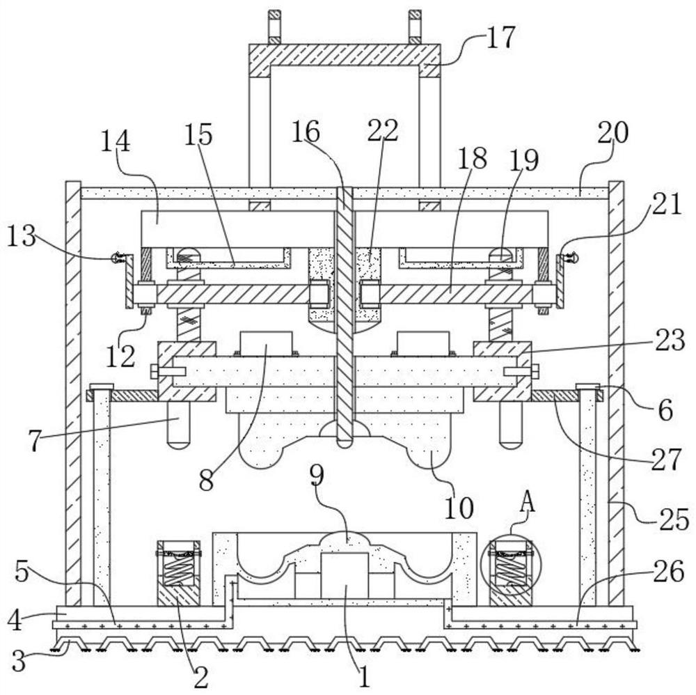
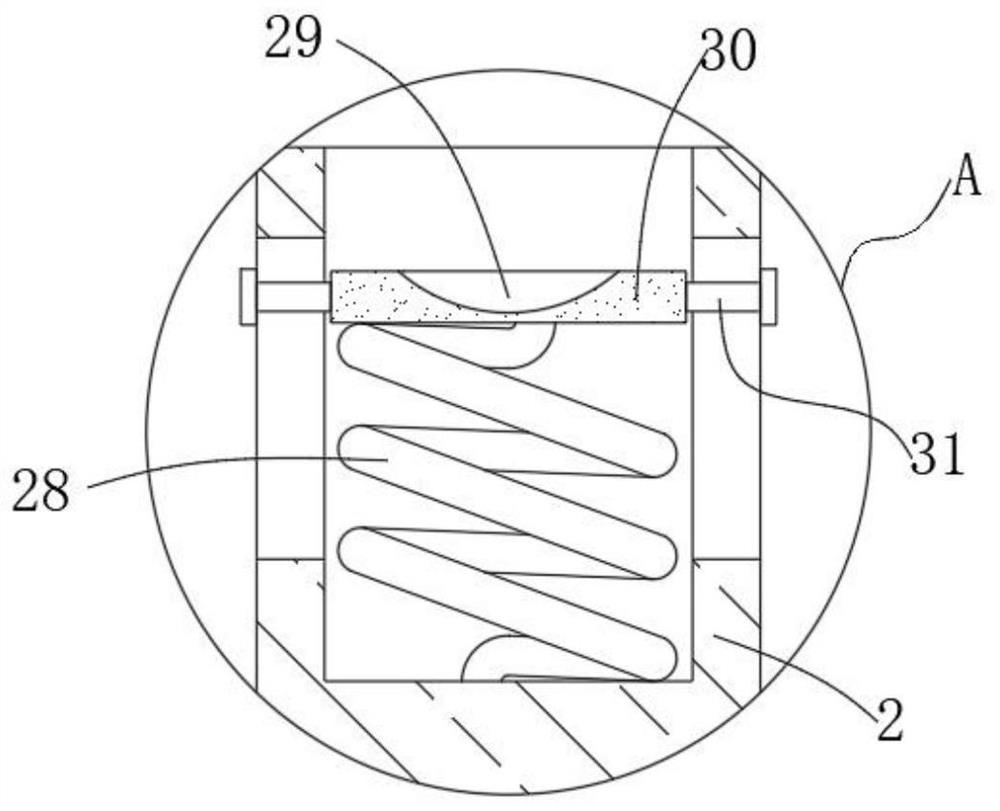
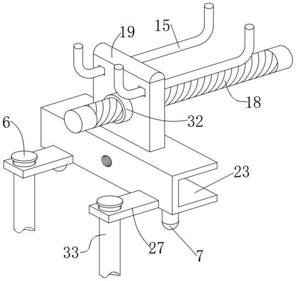
The invention discloses cooling demoulding equipment for a stamping mould, which comprises a bottom plate; a lower mould is fixed to the outer wall of the top of the bottom plate through bolts; a cooling cavity is formed in the lower mould; communicated first pipe holes are formed in the side wall, close to the top, of the cooling cavity and the side wall of the bottom plate; cold inlet pipes are fixedly connected into the first pipe holes; the side wall, close to the bottom, of the cooling cavity and the side wall of the bottom plate are provided with communicated second pipe holes; cold outlet pipes are fixedly connected into the second pipe holes; the top of the bottom plate is provided with an upper mould mechanism; the upper mould mechanism is located over the lower mould; the outer wall of the top of the bottom plate is provided with four buffering mechanisms; and the four buffering mechanisms are located at the four corners close to the lower mould correspondingly. According to the cooling demoulding equipment of the stamping mould in the invention, the equipment has a cooling function for assisting unloading and an unloading function; therefore, after stamping, a stamped workpiece can be rapidly blanked; manual stripping is avoided; and the use convenience of the equipment is improved.

Description

technical field [0001] The invention relates to the technical field of stamping dies, in particular to cooling and demoulding equipment for stamping dies. Background technique [0002] Stamping is a forming processing method that applies external force to plates, strips, pipes and profiles by presses and molds to cause plastic deformation or separation to obtain workpieces (stamping parts) of required shape and size. The blanks for stamping are mainly hot-rolled and cold-rolled steel sheets and strips. [0003] At present, the existing cooling and demoulding equipment for stamping dies has the following deficiencies: the stamping granularity is relatively large, the metal deformation will have a certain rebound after stamping, and the deformation produced by the workpiece will sometimes be attached to the upper mold, requiring manual removal. The material, and the deformation of the workpiece during stamping will be hotter, and it is easy to cause burns during the blanking ...

Claims


Application Information

Patent Timeline
IPC IPC(8): B21D45/08B21D37/12B21D37/16
CPCB21D45/08B21D37/12B21D37/16
Inventor 蒋敏龙
Owner 蒋敏龙
Why Eureka
Try Eureka