
Optical fiber current transformer based on diamond NV color center and measuring method

A technology of optical fiber current and diamond, which is applied in the direction of measuring devices, measuring only current, measuring electrical variables, etc., can solve the problem that the sensor performance depends on the sensitivity intensity, the physical characteristics of optical fiber, the stability and the detection accuracy cannot be well guaranteed and limited. Sensor development and other issues, to achieve the effect of easy system replacement or upgrade, promotion and use, and optimization of spin properties

Active Publication Date: 2021-12-17
ANHUI GUOSHENG QUANTUM TECH CO LTD
View PDF27 Cites 18 Cited by
  • Summary
  • Abstract
  • Description
  • Claims
  • Application Information

AI Technical Summary

Problems solved by technology

Although the research on these two methods has carried out various researches at home and abroad, and has achieved considerable measurement sensitivity, there are still many problems, such as the performance of the sensor is too dependent on the sensitivity of the material to the magnetic field and the physical characteristics of the optical fiber. (length, shape), so that its stability and detection accuracy during use are not well guaranteed, and these factors ultimately limit the development of optical fiber-based magnetic field sensors
[0004] In recent years, the research on diamond NV color centers has opened up infinite possibilities in the field of quantum sensing, especially in the field of magnetic field measurement, the detection method based on ODMR has been developed, and the detection sensitivity below nT has been realized, but these The technology is based on the confocal optical system, the structure is complex, the cost is high, and it is difficult to promote

Method used


Image

  • Optical fiber current transformer based on diamond NV color center and measuring method
  • Optical fiber current transformer based on diamond NV color center and measuring method
  • Optical fiber current transformer based on diamond NV color center and measuring method

Examples


Embodiment 1

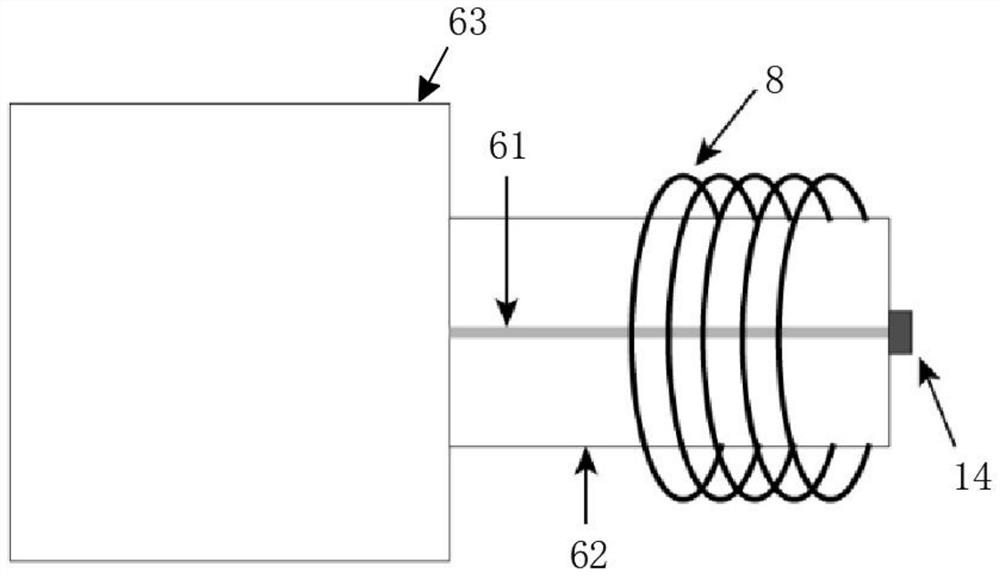
[0064] as attached Figure 1-2 As shown, the present invention provides a novel optical fiber current transformer:

[0065] Including laser excitation and reflected light receiving analysis equipment, diamond NV color center probe, magnet concentrator and microwave excitation equipment;

[0066] Laser excitation and reflected light receiving analysis equipment, used to excite the laser beam to the diamond NV color center probe, and screen the mixed laser beam reflected back by the diamond NV color center probe, and analyze the remaining NV color center reflected fluorescence data ; Preferably, the laser excitation and reflected light receiving analysis equipment includes a laser 1, a mirror 2, a dichromatic film 3, a fiber coupler 4, a filter 5, an optical fiber 6, a photodetector 7, a fluorescence analysis processor 10 and a computer 11. When in use, the laser 1 emits the original laser beam against the reflector 1, that is, the 532nm laser beam, and the reflected original l...

Embodiment 2

[0071]Based on Embodiment 1, this embodiment specifically introduces a non-all-optical measurement method based on the aforementioned fiber optic current transformer. This method has higher sensitivity, but the dynamic range of measurement is small, and it is suitable for measuring conductors with small currents:

[0072] During measurement, the magnetic concentrator 12 is placed on the periphery of the energized conductor 13 to be measured, and the diamond NV color center probe is placed in the magnetic concentrating air gap of the magnetic concentrator 12 (i.e. attached Figure 4 In the middle C-shaped ring fracture), and make the [100] crystal direction of the diamond 14 parallel to the magnetic field in the magnetic gathering air gap, the laser excitation and reflected light receiving analysis equipment emits the original laser beam, and the diamond 14 is irradiated by the original laser beam, At the same time, the microwave source 9 is started, and the microwave source 9 g...

Embodiment 3

[0086] Based on Embodiment 1, this embodiment specifically introduces an all-optical measurement method based on the aforementioned fiber optic current transformer. This method has a larger measurement dynamic range, but lower sensitivity, and is suitable for measuring conductors with large currents:

[0087] When measuring, place the magnetic concentrator on the periphery of the current-carrying conductor to be tested, place the diamond NV color center probe in the magnetic concentrating air gap of the magnetic concentrator, and make the [100] crystal orientation of diamond 14 and the magnetic field in the magnetic concentrating air gap Parallel, the laser excitation and reflected light receiving and analyzing equipment emits the original laser beam, and the diamond 14 is irradiated by the original laser beam, and the fluorescence reflected by the diamond 14 returns to the laser excitation and reflected light receiving and analyzing equipment, and the size of the external magne...


PUM


Abstract

The invention relates to the technical field of current sensors, and provides an optical fiber current transformer based on a diamond NV color center and a measuring method. The optical fiber current transformer comprises laser excitation and reflected light receiving analysis equipment, a diamond NV color center probe, a magnetic concentrator and microwave excitation equipment, wherein the transformer adopts three measurement methods, namely an all-optical measurement method, a non-all-optical measurement method and a combined measurement method. The optical fiber current transformer is simple in structure, high in practicability, capable of resisting external interference and high in robustness, the optical fiber is only used for transmission of exciting light and collection of fluorescent light, thus bending and twisting of the optical fiber do not affect a detection result to a certain extent, and the use is more convenient; in addition, by optimizing the NV color center concentration and the spinning property in the diamond, the sensitivity of magnetic field measurement can be remarkably improved, and the possibility is provided for current measurement with higher precision.

Description

technical field [0001] The invention relates to the technical field of current sensors, in particular to an optical fiber current transformer based on a diamond NV color center and a measurement method. Background technique [0002] For current sensing, there are currently various detection methods. For example, the current-carrying conductor will do mechanical movement in the magnetic field, and then the original mechanical ammeter appears, and there is also a thermocouple instrument that converts current into heat, but these measuring instruments or sensors It will conduct series contact detection with the measurement object, and the result will change the working state of the circuit or energized equipment, and it is difficult to accurately detect the current in the normal working circuit or energized conductor. In order to solve this problem, a non-contact current measurement was proposed later, which uses the magnetic effect of the current to convert the current measure...

Claims


Application Information

Patent Timeline
IPC IPC(8): G01R15/24G01R19/00
CPCG01R15/245G01R19/0092G01R33/26G01R33/0017G01R33/323Y02A90/30G01R15/247
Inventor 赵博文张少春
Owner ANHUI GUOSHENG QUANTUM TECH CO LTD
Learn More