
Precision control mechanism for milling aluminum alloy thin-wall part

A milling and precision control technology, used in metal processing mechanical parts, metal processing, metal processing equipment, etc., can solve the problems of insufficient rotation speed, slow efficiency, aluminum alloy damage, etc., to avoid recycling and avoid falling, rotating The effect of increased speed and avoidance of milling errors

Active Publication Date: 2021-12-17
扬州市吉奥米金属制品有限公司
View PDF2 Cites 2 Cited by
  • Summary
  • Abstract
  • Description
  • Claims
  • Application Information

AI Technical Summary

Problems solved by technology

[0003] In the prior art, due to the aging of equipment during milling of aluminum alloy, the precision of rotary milling will be unstable, and the insufficient rotation speed of milling will slow down the efficiency and cause irreversible damage to aluminum alloy, and with milling, Aluminum alloy chips will continue to be produced, affecting the contact surface between the milling mechanism and the aluminum alloy, and falling into the equipment to damage the equipment

Method used


Image

  • Precision control mechanism for milling aluminum alloy thin-wall part
  • Precision control mechanism for milling aluminum alloy thin-wall part
  • Precision control mechanism for milling aluminum alloy thin-wall part

Examples


Embodiment 1

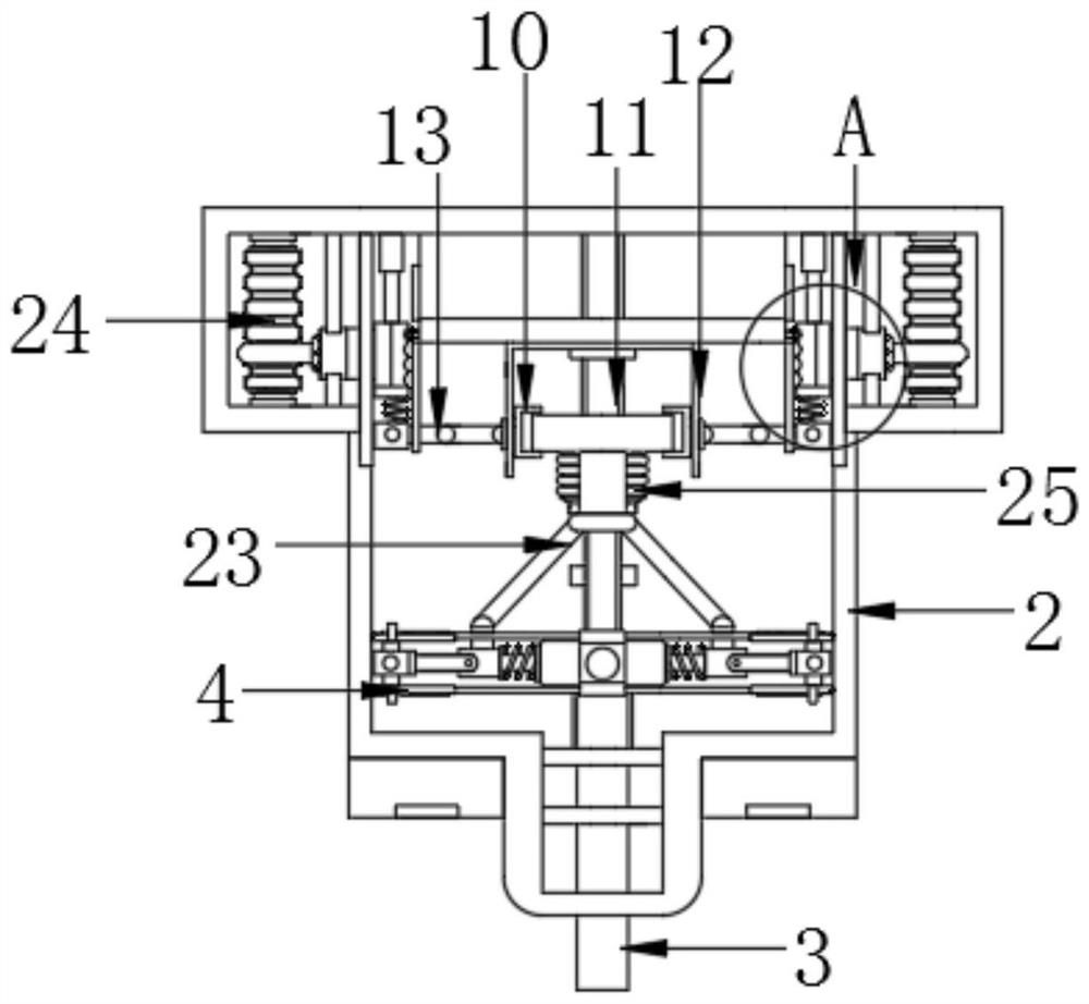
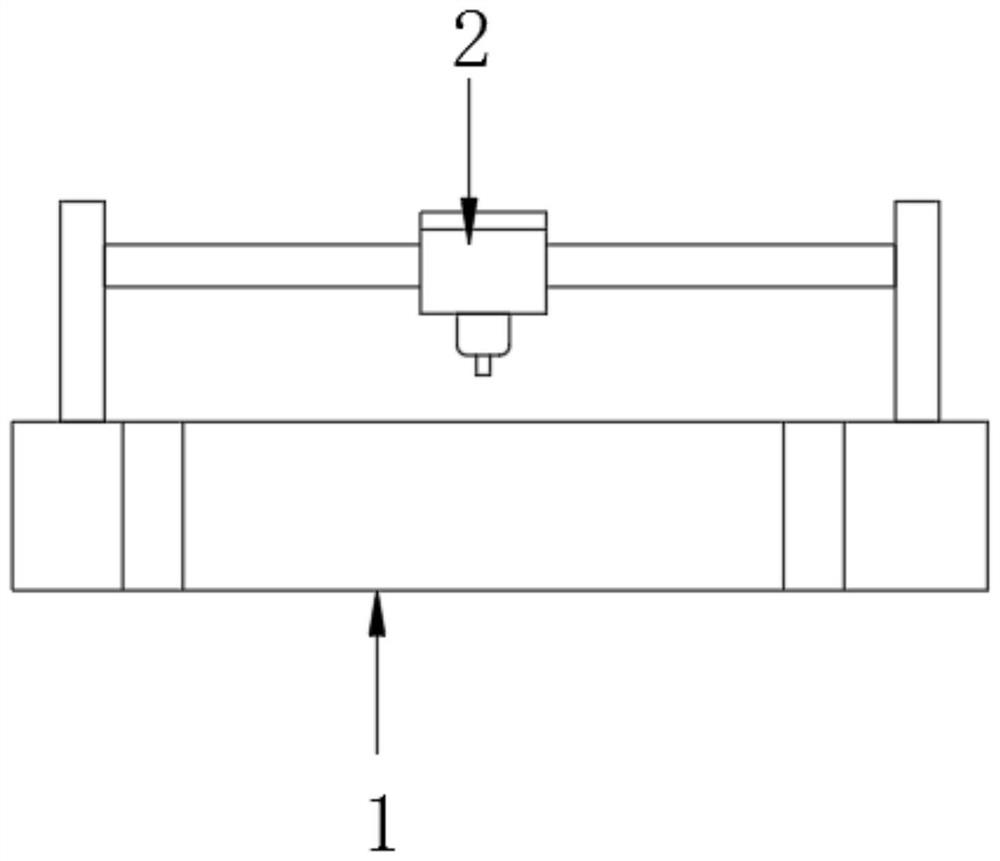
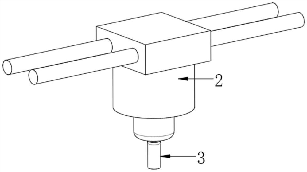
[0029] see figure 1 and 6 , a precision control mechanism for milling aluminum alloy thin-walled parts, comprising a base 1, the top of the base 1 is movably connected to a milling mechanism 2, the inner wall of the milling mechanism 2 is rotatably connected to a milling cutter 3, and the top of the milling cutter 3 is fixed Connected with a milling rotary mechanism 23, the outer wall of the milling rotary mechanism 23 is movably connected with a ring clip 10, the inner wall of the milling rotary mechanism 23 is fixedly connected with a telescopic rod 11, and the outer wall of the ring clip 10 is slidably connected with a vertical rail 12, the ring A lever 13 is hinged on the side of the sleeve clamp 10 away from the telescopic rod 11 , and an end of the lever 13 away from the sleeve clamp 10 is movably connected with a clamping mechanism 24 , and the top of the milling rotation mechanism 23 is movably connected with a recovery mechanism 25 .

[0030] Further, the clamping me...

Embodiment 2

[0033] see figure 1 and 7 , a precision control mechanism for milling aluminum alloy thin-walled parts, comprising a base 1, the top of the base 1 is movably connected to a milling mechanism 2, the inner wall of the milling mechanism 2 is rotatably connected to a milling cutter 3, and the top of the milling cutter 3 is fixed Connected with a milling rotary mechanism 23, the outer wall of the milling rotary mechanism 23 is movably connected with a ring clip 10, the inner wall of the milling rotary mechanism 23 is fixedly connected with a telescopic rod 11, and the outer wall of the ring clip 10 is slidably connected with a vertical rail 12, the ring A lever 13 is hinged on the side of the sleeve clamp 10 away from the telescopic rod 11 , and an end of the lever 13 away from the sleeve clamp 10 is movably connected with a clamping mechanism 24 , and the top of the milling rotation mechanism 23 is movably connected with a recovery mechanism 25 .

[0034] Further, the recovery me...

Embodiment 3

[0037] see Figure 1-7 , a precision control mechanism for milling aluminum alloy thin-walled parts, comprising a base 1, the top of the base 1 is movably connected to a milling mechanism 2, the inner wall of the milling mechanism 2 is rotatably connected to a milling cutter 3, and the top of the milling cutter 3 is connected to the The runner rail 4 is fixedly connected, the outer wall of the ring layer 8 is movably connected with the ring clip 10, and the outer wall of the milling cutter 3 is in contact with the aluminum alloy.

[0038]The top of milling cutter 3 is fixedly connected with milling rotary mechanism 23, and milling rotary mechanism 23 comprises runner rail 4, and the inner wall of runner rail 4 is fixedly connected with centrifugal spring 5, and one end of centrifugal spring 5 away from runner rail 4 is fixedly connected with sliding Block 6, the positive and negative sides of the slider 6 are slidingly connected with the runner rail 4, the outer wall of the ce...


PUM


Abstract

The invention relates to the technical field of aluminum alloy milling, and provides a precision control mechanism for an aluminum alloy thin-wall part milling. The precision control mechanism comprises a base. The top of the base is movably connected with a milling mechanism, the inner wall of the milling mechanism is rotationally connected with a milling cutter, the top of the milling cutter is fixedly connected with a milling rotating mechanism, and the outer wall of the milling rotating mechanism is movably connected with a ring sleeve clamp. According to the precision control mechanism for milling the aluminum alloy thin-wall part, at the beginning, the milling cutter normally rotates, a sliding block stretches a centrifugal spring under the action of centrifugal force, when the milling speed of the milling cutter is reduced, the sliding block gets close to the position of a rotating shaft under the action of the elastic force of the centrifugal spring, the sliding block jacks up a ring sleeve layer through a linkage rod, the ring sleeve layer jacks up a ring sleeve clamp, the ring sleeve clamp slides along a vertical rail and changes the height of a pull block through a lever, the pull block pushes a pull plate through a top spring, the pull plate moves to reduce the resistance value of a rheostat, and the rotating speed of the milling cutter is increased.

Description

technical field [0001] The invention relates to the technical field of aluminum alloy milling, in particular to a precision control mechanism for milling aluminum alloy thin-walled parts. Background technique [0002] Aluminum alloy is an alloy based on aluminum with a certain amount of other alloying elements added. It is one of the light metal materials. With the development of the times, people's living areas continue to expand and buildings continue to increase. Steel, with good corrosion resistance and weldability, is widely used, and aluminum alloy is processed by milling to produce the desired shape. [0003] In the existing technology, due to the aging of equipment during milling of aluminum alloy, the precision of rotary milling will be unstable. The insufficient rotation speed of milling will slow down the efficiency and cause irreversible damage to aluminum alloy, and with milling, Aluminum alloy chips will continue to be generated, affecting the contact surface ...

Claims


Application Information

Patent Timeline
Patent Type & Authority Applications(China)
IPC IPC(8): B23Q15/08B23Q11/00
CPCB23Q15/08B23Q11/0046
Inventor 陈强杨平
Owner 扬州市吉奥米金属制品有限公司
Learn More