Anti-radiation packaging structure and method

A packaging structure, anti-radiation technology, applied in the direction of electrical components, electrical solid devices, circuits, etc.

Pending Publication Date: 2021-12-14
重庆平创半导体研究院有限责任公司
View PDF10 Cites 0 Cited by
  • Summary
  • Abstract
  • Description
  • Claims
  • Application Information

AI Technical Summary

Problems solved by technology

However, as modern electronic equipment systems require miniaturization, low cost, and high integration, the traditional anti-radiation results of shielding cables through ceramic packaging or metal packaging can no longer meet the current needs.

Method used


Image

  • Anti-radiation packaging structure and method
  • Anti-radiation packaging structure and method

Examples


Embodiment 1

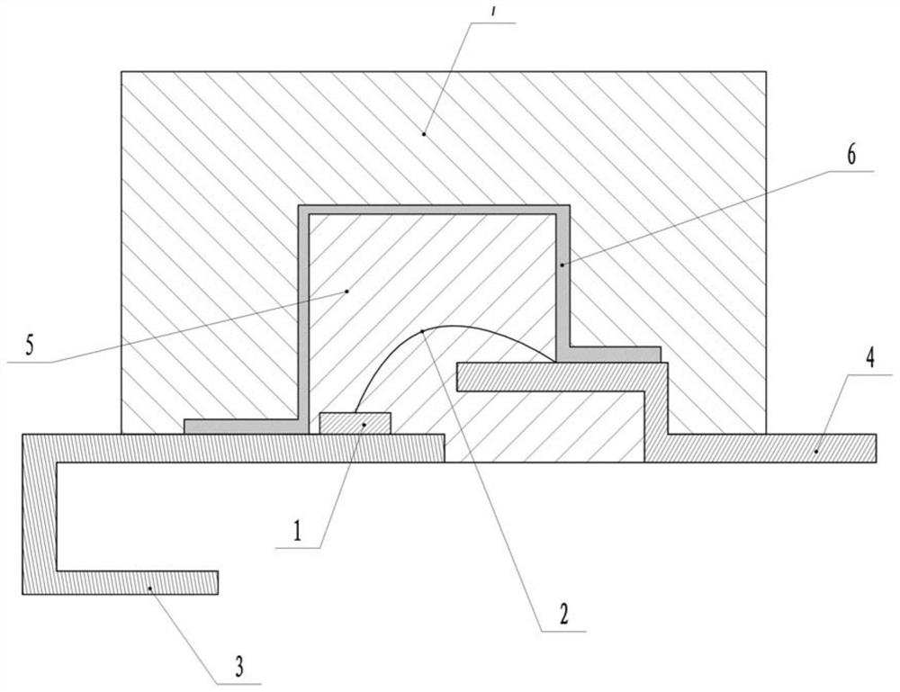
[0051] Embodiment one is basically as attached figure 1 Shown: a radiation-resistant packaging structure, including an embedded shell 6, and a first plastic package 5 and a second plastic package 7 for plastic packaging the device to be plastic packaged.

[0052] The device to be plastic-encapsulated includes a substrate 3 , pins 4 , a chip 1 and a bonding wire 2 , the chip 1 is fixedly connected to the substrate 3 through solder paste, and the chip 1 and the pins 4 are interconnected through the bonding wire 2 .

[0053] In this embodiment, when the first plastic package 5 is plastic-sealed, the chip 1 and the bonding wire 2 are arranged inside the first plastic package 5, so that the plastic packaging requirements of this time are completed, and it is also for the purpose of achieving Radiation resistance requirements of chip 1 and bonding wire 2. The embedded shell 6 is turned upside down on the outer surface of the first plastic package 5 to meet the radiation resistance ...


PUM


Abstract

The invention relates to the technical field of integrated circuit packaging, and particularly discloses an anti-radiation packaging structure, which comprises an embedded shell, and a first plastic package part and a second plastic package part which are used for carrying out plastic package on a device to be subjected to plastic package, the embedded shell is inversely buckled on the outer surface of the first plastic package part, and the embedded shell is fixedly connected with the device to be subjected to plastic package through soldering paste; the second plastic package part wraps the embedded shell. The invention further discloses an anti-radiation packaging method based on the structure. According to the invention, the embedded shell is arranged between the first plastic package part and the second plastic package part, that is to say, the anti-radiation function is realized by using the own specificity of the embedded housing, and compared with the prior art, the embedded shell covers the packaging part, so that the corresponding weight can be reduced on the premise of meeting the anti-radiation requirement of the to-be-packaged device and keeping the overall size unchanged.

Description

technical field [0001] The invention relates to the technical field of integrated circuit packaging, in particular to an anti-irradiation packaging structure and method. Background technique [0002] With the continuous development of industrial technology fields such as aerospace and weaponry, integrated circuit packaging products have been widely used. Considering the ubiquitous situation of cosmic rays in the space environment, it is necessary for the corresponding packaging products to have the ability to withstand high-energy particles. It has the advantages of long-term use and high reliability during radiation. At present, the most common packaging methods are through ceramic packaging or metal packaging. However, as modern electronic equipment systems require miniaturization, low cost, and high integration, the traditional anti-radiation results of shielding cables through ceramic packaging or metal packaging can no longer meet the current needs. [0003] Therefore...

Claims


Application Information

Patent Timeline
Patent Type & Authority Applications(China)
IPC IPC(8): H01L23/552H01L23/31H01L21/50H01L21/56
CPCH01L23/552H01L23/3135H01L21/50H01L21/56
Inventor 钱靖任真伟陈显平罗厚彩
Owner 重庆平创半导体研究院有限责任公司
Why Eureka
Try Eureka