
Online monitoring method for looseness of flange connecting bolt

A technology for connecting bolts and flanges, which is applied in the field of online monitoring of flange connection bolt loosening, can solve the problems of inability to effectively display the bolt loosening state and load state, and inability to effectively monitor tangential displacement, and achieve the effect of high monitoring sensitivity.

Pending Publication Date: 2021-12-14
陕西中科启航科技有限公司
View PDF0 Cites 2 Cited by
  • Summary
  • Abstract
  • Description
  • Claims
  • Application Information

AI Technical Summary

Problems solved by technology

The axial displacement in the middle of the flange is very small, but there may be a large tangential displacement along the edge of the flange between the upper and lower flanges. The axial displacement sensor installed in this part may not be able to effectively monitor the tangential displacement and cannot effectively display Bolt loose state and load state in the middle of the flange

Method used


Image

  • Online monitoring method for looseness of flange connecting bolt
  • Online monitoring method for looseness of flange connecting bolt
  • Online monitoring method for looseness of flange connecting bolt

Examples


Embodiment 1

[0049] refer to Figure 1 to Figure 9 , the invention provides a method for on-line monitoring of flange connection bolt looseness, comprising the following steps:

[0050] S1. Four displacement sensors 16 are evenly arranged on the inner or outer circumference of the flange connection;

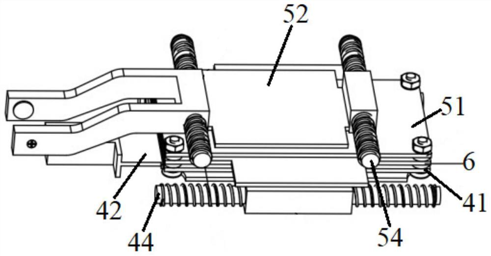
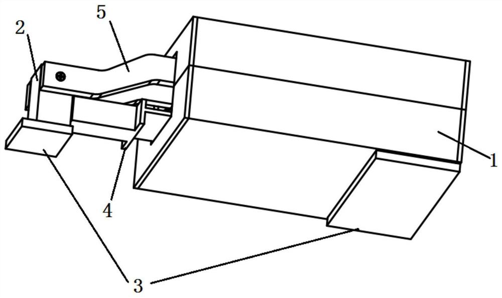
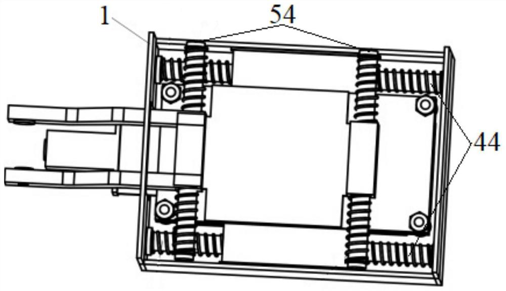
[0051] The displacement sensor at least includes a housing 1, a limit block 2 and a sensing module located in the housing, which are used to monitor the displacement changes of the upper and lower flanges. Specifically, when the mounting surface of the limit block and the housing are on the same plane, The limit block and the housing are directly fixed on the two measured parts. When the mounting surfaces of the limit block and the housing are on different planes, the limit block and the housing are fixed on the two parts through the installation pad 3. on the component under test, such as figure 2 and Figure 4 As shown, by adjusting the thickness of the limit block or the mounting pad c...

Embodiment 2

[0080] The structure of the displacement sensor used in this embodiment is basically the same as that of Embodiment 1. The difference is that there is only one connecting rod in this embodiment, such as Figure 10 to Figure 11 As shown, at this time, there is a mounting hole on the limit block along the installation direction of the sensor. The mounting hole runs through the limit block. During the lateral relative displacement, the limit block drives the connecting rod to move laterally to the left or right, thereby driving the lateral sliding base to move. The surface of the mounting hole is smooth, so that when the upper and lower flanges are displaced longitudinally, the limiting block and the connecting rod move longitudinally relative to each other without affecting the lateral sliding base.

[0081] The present invention provides an on-line monitoring method for flange connection bolt looseness, which simultaneously considers the relative displacement along the axial di...


PUM


Abstract

The invention provides an online monitoring method for looseness of a flange connecting bolt, which comprises the following steps: arranging a group of displacement sensors at a flange connecting part, respectively measuring transverse and longitudinal displacements of each sensor under different main load conditions in a test or CAE finite element analysis scene and an actual flange working condition, and comparing and judging whether the flange bolt is severely loosened or fractured. According to the invention, the relative displacement between the two measuring points in the axial direction of the flange and the relative displacement between the two measuring points in the tangential direction of the edge of the flange are considered at the same time, the two displacements are both related to bolt looseness or fracture, and the problem of serious bolt looseness or fracture can be monitored more accurately; and the method has the advantages of being sensitive to bolt loosening response, high in monitoring result precision, wide in application range and low in cost.

Description

technical field [0001] The invention relates to an online monitoring method for flange connection bolt looseness, which belongs to the field of flange bolt monitoring. Background technique [0002] Flange connection refers to a detachable connection consisting of flanges, gaskets and bolts connected to each other as a combined sealing structure. Flange connection structures are extremely common in the current industrial field and play a very important role. The bolts in the flange connection structure are subjected to tension and compression cycles under alternating loads. Under the action of alternating tension and compression loads, the plastic deformation of the thread leads to relaxation, which will lead to a decrease in the pre-tightening force of the bolt. If the pre-tightening force is too small, the connection will be unreliable, and phenomena such as vibration relaxation, leakage, and structural slippage will occur during work, which will affect the normal operatio...

Claims


Application Information

Patent Timeline
IPC IPC(8): G01L5/24
CPCG01L5/24Y02E10/72
Inventor 田琦程庆阳王东利
Owner 陕西中科启航科技有限公司
Learn More