


Quick Research
Generate reliable direction feasibility study reports for your R&D in just a few steps.

Technical Q&A
Discover and master advanced knowledge NOW. Basics, ideas, possibilities, all at once.

Find Solutions
As an expert in R&D theories, this can generate solutions to your technical problems instantly.

Evaluate Feasibility
Analyze your overall solution with one click, know your potential R&D risks in advance.

Monitor Landscape
Get weekly tech updates, stay abreast of the latest tech innovations and key insights.
Natural gas liquefaction treatment device adopting composite refrigeration liquefaction
A technology for liquefied natural gas and liquefaction treatment, which is applied in the field of compound refrigeration liquefied natural gas liquefaction treatment devices, and can solve the problems affecting the purity and mixing of liquefied natural gas
- Summary
- Abstract
- Description
- Claims
- Application Information
AI Technical Summary
Problems solved by technology
Method used
Image

Examples
Embodiment 1
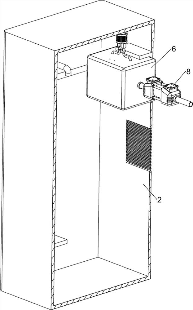
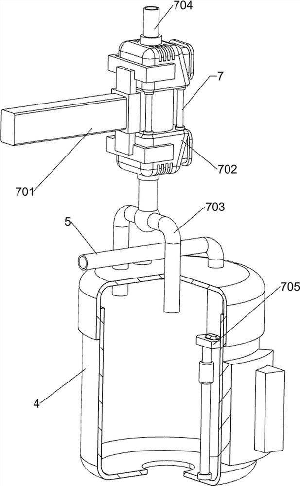
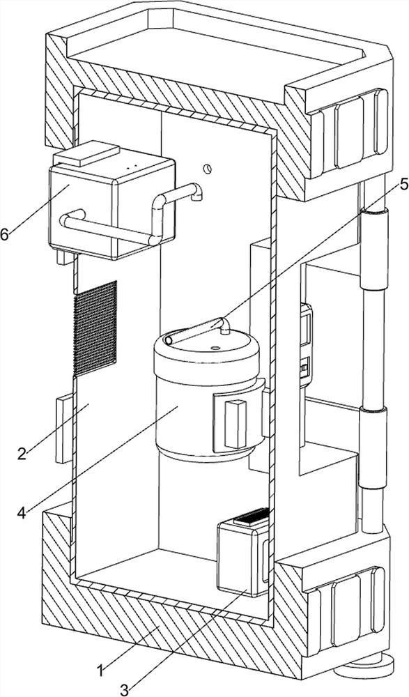
[0040] A compound refrigeration liquefied natural gas liquefaction treatment device, such as figure 1 , figure 2 , image 3 , Figure 4 , Figure 5 , Figure 6 , Figure 7 , Figure 8 , Figure 9 , Figure 10 , Figure 11 and Figure 17 As shown, it includes a base 1, a casing 2, a sealed tank 4, a natural gas inlet pipe 5, a condensation box 6, an air extraction component 7, a condensation component 8, a drainage component 9 and a water injection component 12, and the top of the base 1 is fixedly connected with the casing 2, The middle part of the casing 2 is connected with a sealed tank 4 by bolts, and the bottom of the sealed tank 4 has a water outlet. The left side of the inner wall is equipped with an air extraction assembly 7, which is connected between the airtight tank 4 and the condensation box 6, the condensation box 6 is provided with a condensation assembly 8, the lower part of the airtight tank 4 is provided with a drainage assembly 9, and the inner wal...
Embodiment 2
[0047] On the basis of Example 1, such as Figure 12 , Figure 13 , Figure 14 , Figure 15 , Figure 16 , Figure 18 and Figure 19 As shown, a control assembly 10 is also included, and the control assembly 10 includes a first air intake pipe 1001, a ball valve 1002, a second gear 1003, a second guide sleeve 1004, a U-shaped rod 1005, a first spring 1006 and a second rack 1007 The left side of the natural gas intake pipe 5 is connected with a first intake pipe 1001, a ball valve 1002 is rotated on the first intake pipe 1001, a second gear 1003 is connected to the front and rear sides of the ball valve 1002, and a second gear 1003 is connected to the front and rear symmetrically on the left side of the sealed tank 4. U-shaped rod 1005 is slidingly arranged between the second guide sleeve 1004 and the second guide sleeve 1004, and the upward movement of the first baffle plate 901 will drive the U-shaped rod 1005 to move upward, and the front and back between the U-shaped r...
PUM
 Abstract
Description
Claims
Application Information
 - R&D Engineer
- R&D Manager
- IP Professional
- Industry Leading Data Capabilities
- Powerful AI technology
- Patent DNA Extraction
Browse by: Latest US Patents, China's latest patents, Technical Efficacy Thesaurus, Application Domain, Technology Topic, Popular Technical Reports.
© 2024 PatSnap. All rights reserved.Legal|Privacy policy|Modern Slavery Act Transparency Statement|Sitemap|About US| Contact US: help@patsnap.com