


Quick Research
Generate reliable direction feasibility study reports for your R&D in just a few steps.

Technical Q&A
Discover and master advanced knowledge NOW. Basics, ideas, possibilities, all at once.

Find Solutions
As an expert in R&D theories, this can generate solutions to your technical problems instantly.

Evaluate Feasibility
Analyze your overall solution with one click, know your potential R&D risks in advance.

Monitor Landscape
Get weekly tech updates, stay abreast of the latest tech innovations and key insights.
Underground rock cavity, underground rock cavity forming system and energy storage system based on underground rock cavity
A technology of rock formations and carbonates, applied in the field of energy storage systems, can solve problems such as doubtful stability and safety, limited terrain conditions, limited energy density, etc., and achieve the effects of easy mining and processing, reduced formation costs, and high energy density
- Summary
- Abstract
- Description
- Claims
- Application Information
AI Technical Summary
Problems solved by technology
Method used
Image

Examples
Embodiment 1
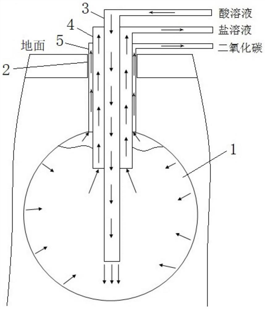
[0048] Embodiment 1, an underground rock cavity with a carbonate rock layer as the formation area, by injecting an acid solution into the carbonate rock layer, the acid solution dissolves the carbonate and reacts to generate a salt solution and carbon dioxide, and the salt solution and carbon dioxide generated by the reaction are discharged. After carbon dioxide, the underground cavity is formed at the location of the carbonate formation. The size of the underground rock cavity is adjusted by adjusting the injection amount of the acid solution, so that the underground rock cavity can meet the needs of different scenarios.
[0049] see figure 1 , the formation system of the underground rock cavity shown in , select the carbonate rock layer as the formation area of the underground rock rock layer 1, drill a borehole 2 connected with the carbonate rock layer from the ground, and drill to the carbonate rock layer through the hole Acid solution is injected, the acid solution dis...
Embodiment 2
[0064] Embodiment 2, a system for forming an underground rock cavity, including a borehole, a liquid injection pipeline, a liquid drainage pipeline and an exhaust pipeline, one end of the liquid injection pipeline extends into the underground carbonate rock formation, and the other end As an acid solution injection port, one end of the drainage pipeline and the exhaust pipeline extend into the underground carbonate rock formation, and the other ends are respectively used as a saline solution and a carbon dioxide discharge outlet.
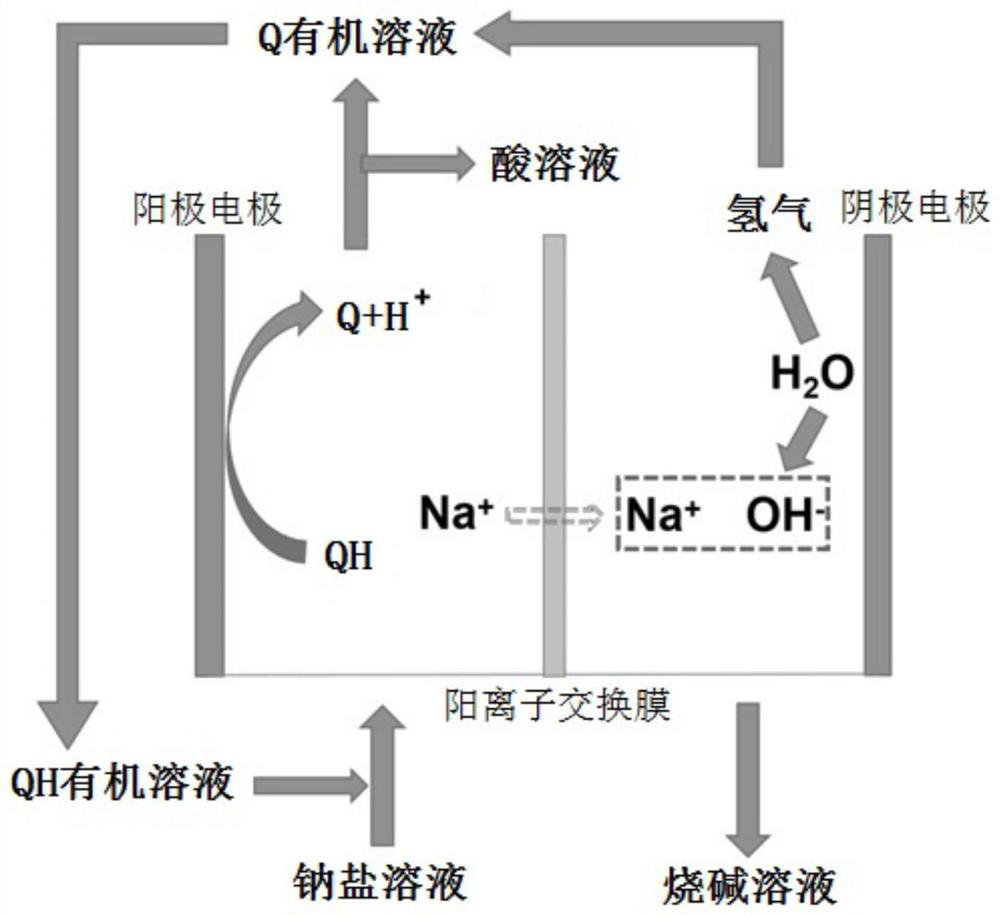
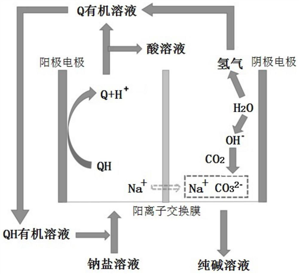
[0065] The underground rock cavity formation system is connected with the two alkali production components, the two alkali production components include an electrolytic cell, a cation exchange membrane that divides the electrolytic cell into an anode area and a cathode area, an anode electrode arranged in the anode area and an anode electrode arranged in the The cathode electrode in the cathode area; the liquid outlet of the anode area communicates w...
Embodiment 3
[0073] Embodiment 3, a pumped storage power station based on underground rock cavity, see Figure 5 , including an upper reservoir 1 and an underground lower reservoir 2, the upper reservoir 1 and the lower reservoir 2 are connected through a water delivery channel, and a two-way generator set 3 is arranged on the water delivery channel, and the upper reservoir 1 is an ocean , lakes, rivers or surface artificial reservoirs; the lower reservoir 2 is the underground rock cavity described in Embodiment 1.
[0074] The two-way generating set includes a water pump and a water turbine. When power generation is required, water flows from the upper reservoir 1 to the lower reservoir 2 to drive the water turbine of the two-way generating set 3 to generate electricity. When the energy is surplus, the water in the lower reservoir 2 is pumped back to the upper reservoir by the water pump of the bidirectional generator set 3 to complete energy storage.
[0075] The water level difference ...
PUM
| Property | Measurement | Unit |
|---|---|---|
| thickness | aaaaa | aaaaa |
| thickness | aaaaa | aaaaa |
Abstract
Description
Claims
Application Information
 - R&D Engineer
- R&D Manager
- IP Professional
- Industry Leading Data Capabilities
- Powerful AI technology
- Patent DNA Extraction
Browse by: Latest US Patents, China's latest patents, Technical Efficacy Thesaurus, Application Domain, Technology Topic, Popular Technical Reports.
© 2024 PatSnap. All rights reserved.Legal|Privacy policy|Modern Slavery Act Transparency Statement|Sitemap|About US| Contact US: help@patsnap.com