Glass tempering treatment equipment and dedicated liquid washing mechanism thereof

A technology for processing equipment and special fluids, used in metal processing equipment, grinding/polishing equipment, machine tools suitable for grinding the edge of workpieces, etc.

Active Publication Date: 2021-12-10
平邑华玉节能玻璃有限公司
View PDF10 Cites 0 Cited by
  • Summary
  • Abstract
  • Description
  • Claims
  • Application Information

AI Technical Summary

Problems solved by technology

[0005] The object of the present invention is to provide a glass tempering treatment equipment and its special liquid washing mechanism to solve the problem that the existing grinding equipment proposed in the above background technology cannot clean up the glass debris generated after grinding after grinding the surroundings of the glass. The problem of poor grinding effect

Method used


Image

  • Glass tempering treatment equipment and dedicated liquid washing mechanism thereof
  • Glass tempering treatment equipment and dedicated liquid washing mechanism thereof
  • Glass tempering treatment equipment and dedicated liquid washing mechanism thereof

Examples


Embodiment 1

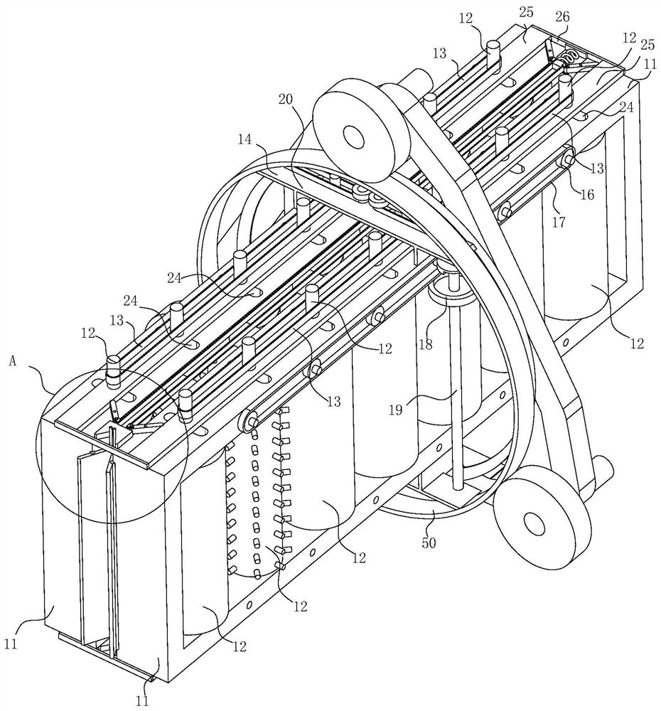
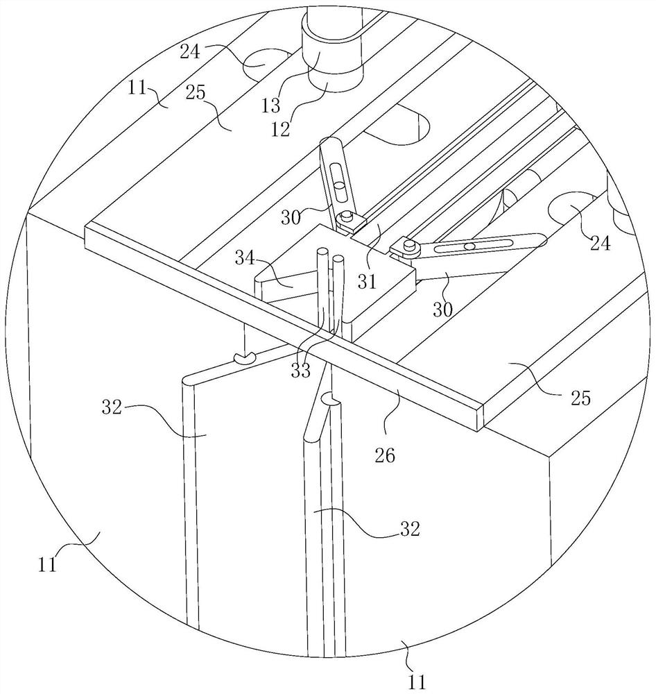
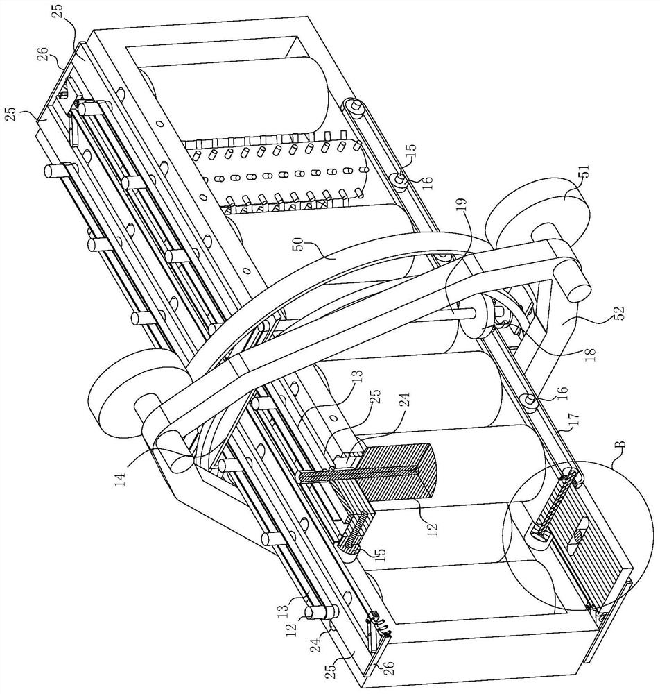
[0081] see Figure 1-9, the present invention provides a technical solution: a glass tempering treatment equipment, including a motor 10 and two sets of symmetrical fixed rectangular frames 11, the motor 10 is fixedly installed in the center of the lower ends of the two sets of rectangular frames 11 through brackets, and the two rectangular frames 11 A plurality of polishing rollers 12 are vertically arranged at equal intervals on the inner wall, and the driving shafts of the polishing rollers 12 on the same side pass through the upper end of the side wall of the rectangular frame 11 and are respectively sleeved with a polishing timing belt 13 on the outer wall. In order to change the power switching mechanism 14 for changing the rotation direction of the left and right side polishing sticks 12, a plurality of equal-spaced grinding wheels 15 for grinding the sides of the glass are rotated between the side walls where the lower ends of the two rectangular frames 11 are close to ...

Embodiment 2

[0101] see Figure 10-15 , a special liquid washing mechanism, comprising: a housing 61, a cover plate 62, a control unit fixedly mounted on the bottom of the cover plate 62, a rotating unit for movably adapting the control unit, the control unit Including a liquid storage shell 71 and an infusion sleeve 72, the bottom of the housing 61 is provided with a liquid outlet, the top of the housing 61 is fixedly connected with the cover plate 62, and the top of the cover plate 62 is provided with an inlet The liquid port, the bottom of the cover plate 62 is fixedly connected with the liquid storage shell 71, the bottom of the liquid storage shell 71 is evenly opened with a delivery port, and the bottom of the liquid storage shell 71 is fixedly connected with the infusion sleeve 72 , the rotating unit is movably disposed inside the casing 61 . Further, the liquid inlet port communicates with the liquid storage shell 71 , and the infusion port is provided corresponding to the infusio...


PUM


Abstract

The invention discloses glass tempering treatment equipment and a dedicated liquid washing mechanism thereof. The dedicated liquid washing mechanism comprises a shell, a cover plate, a control unit and a rotating unit, and the control unit is fixedly installed at the bottom of the cover plate; the rotating unit is used for movably adapting to the control unit; the control unit comprises a liquid storage shell and a liquid conveying sleeve; a liquid outlet is formed in the bottom of the shell, the cover plate is fixedly connected to the top of the shell, a liquid inlet is formed in the top of the cover plate, the liquid storage shell is fixedly connected to the bottom of the cover plate, liquid conveying openings are evenly formed in the bottom of the liquid storage shell, the liquid conveying sleeve is fixedly connected to the bottom of the liquid storage shell, and the rotating unit is movably arranged in the shell; and glass washing liquid enters the liquid storage shell through the liquid inlet in the cover plate, enters the liquid conveying sleeve through the liquid conveying openings and then flows out of the liquid conveying sleeve, the rotating unit in rotation is washed, and ground glass fragments in the rotating unit are removed.

Description

technical field [0001] The invention relates to the technical field of glass tempering, in particular to a glass tempering treatment equipment and its special liquid washing mechanism Background technique [0002] Tempered glass is also called tempered glass. It uses physical or chemical methods to form a compressive stress layer on the glass surface. The glass itself has high compressive strength and will not cause damage. When the glass is subjected to external force, this pressure layer can part of the tensile stress. Offset to avoid glass breakage, although the inside of the tempered glass is in a state of relatively large tensile stress, but there are no defects inside the glass and will not cause damage, thereby achieving the purpose of increasing the strength of the glass. [0003] Existing grinding equipment cannot clean up the glass debris produced after grinding after grinding the surroundings of the glass, and the grinding effect is not good. [0004] Based on t...

Claims


Application Information

Patent Timeline
Patent Type & Authority Applications(China)
IPC IPC(8): B24B9/08B24B27/00B24B29/02B24B55/06B24B41/02B24B41/06
CPCB24B9/08B24B27/0076B24B29/02B24B55/06B24B41/02B24B41/06
Inventor 刘达军王进东
Owner 平邑华玉节能玻璃有限公司
Why Eureka
Try Eureka