Intelligent bone traction tool, traction system and traction method

A bone traction and intelligent technology, applied in intelligent bone traction tools, traction systems and traction fields, can solve problems such as prone to bed sores, slippage of traction needles, traction needle eye infection, etc., to ensure the effect of traction, reduce contact effects, and reduce bedsores risk effect

Pending Publication Date: 2021-12-10
WEST CHINA HOSPITAL SICHUAN UNIV
View PDF6 Cites 2 Cited by
  • Summary
  • Abstract
  • Description
  • Claims
  • Application Information

AI Technical Summary

Problems solved by technology

[0003] However, the current conventional traction tools do not have the function of monitoring traction force data, and when continuous traction is required, the changes in traction force of the patient cannot be obtained in time, and the traction needle may slip due to too small traction force, which further leads to infection of the traction needle eye; It may cause pain or even pierce important deep tissues due to excessive traction force, so it cannot be fed back to the medical staff in time when the traction force changes too much, thus affecting the effect of traction; at the same time, the medical staff cannot obtain continuous "time- Therefore, it is impossible to effectively know the real-time traction state of the patient and the actual traction process
At the same time, the local tissues will completely contact the bed surface under the action of gravity during traction, and decubitus ulcers are prone to occur at the bony protrusions. Bone traction does not do a good job of preventing decubitus ulcers
Traction thimbles generally have a thicker needle tip, which can easily cause tissue damage at the insertion point of the skull

Method used


Image

  • Intelligent bone traction tool, traction system and traction method
  • Intelligent bone traction tool, traction system and traction method
  • Intelligent bone traction tool, traction system and traction method

Examples


Embodiment Construction

[0036] The invention is further illustrated below in conjunction with the accompanying drawings and specific embodiments.

[0037] It should be noted that if the present invention relates to directionality indicating terms, such as above, lower, left, right, before, and later, in order to facilitate the description of the relative positional contact between the members, it is not related to the related components, and the components The absolute position of the relationship refers to, which is only used to explain the relative positional relationship between the components in a particular attitude, and the movement condition, etc., if the specific posture changes, the directional indication is also correspondingly changed. If there is a number of words involved in the present invention, such as "more", "multiple", "several", etc., the specific refers to two and more than two or more.

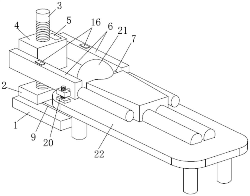
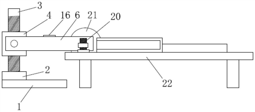
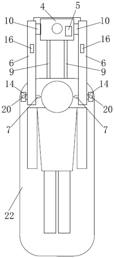
[0038] like Figure 1 to 5As shown in the present invention, the intelligent bone traction tool, ...


PUM


Abstract

The invention discloses an intelligent bone traction tool, traction system and traction method, belongs to the field of medical equipment, and is used for intelligently monitoring traction force. The intelligent bone traction tool comprises a traction arm mounting frame, two traction arms and two traction thimbles, wherein the two traction arms are distributed in a bilateral symmetry mode, one ends of the traction arms are connected with the traction arm mounting frame, the traction ejector pins are mounted at the other ends of the traction arms, and the traction ejector pins mounted on the two traction arms are oppositely arranged. A bone clamping area is formed between the two traction ejector pins, and each traction ejector pin is provided with a pressure sensor capable of monitoring the traction force. According to the intelligent bone traction tool, the pressure sensors capable of monitoring the traction force are arranged on the traction ejector pins, then traction force data can be monitored through the pressure sensors, the situation that the traction force is too large in change and the like can be fed back to medical staff in time so that adjustment can be performed in time, and the traction effect is guaranteed.

Description

Technical field [0001] The present invention relates to the field of medical equipment, and more particularly to a smart bone traction tool, a traction system and a traction method. Background technique [0002] The bone graching is a specific portion of the distal end of the affected limb, under sterile conditions, the bone rermal needle or traction clamp into the bone, and the traction device is used. The bone traction is direct traction, because the traction is a direct role of bones, so it can withstand a large traction weight, the traction is large, and the resistance is small, and it is persistent, which is the most commonly used method for continuous traction. Various bone gradation is a slow reset by fixing the fracture and dislocation of the fracture and dislocation of the bone needle, traction bow, rope, tractor and traction weight, and the traction weight. Clinical common bone traction is as follows: 1. Skull traction; 2. Tibijjjjjjjjjjjjjjjjj [0003] However, there i...

Claims


Application Information

Patent Timeline
Patent Type & Authority Applications(China)
IPC IPC(8): A61B17/66
CPCA61B17/66A61B2017/00022
Inventor 马立泰张翔杨毅刘浩甘芳吉田鹏
Owner WEST CHINA HOSPITAL SICHUAN UNIV
Why Eureka
Try Eureka