Eureka AIR delivers breakthrough ideas for toughest innovation challenges, trusted by R&D personnel around the world.

Vehicle-mounted road surface detection robot

A robot and pavement technology, applied in instruments, measurement devices, radio wave measurement systems, etc., can solve the problems of ground penetrating radar module collision, better disassembly, complicated operation, inaccurate data collection, etc., to achieve good anti-collision performance, High practical value and promotion value, convenient connection effect

Pending Publication Date: 2021-12-07
上海圭目机器人有限公司
View PDF0 Cites 1 Cited by
  • Summary
  • Abstract
  • Description
  • Claims
  • Application Information

AI Technical Summary

Problems solved by technology

Then, the vehicle-mounted road surface detection robot in the prior art just has the problem that the ground penetrating radar module collides with the ground
In addition, the ground-penetrating radar module in the prior art is also equipped with an independent traveling mechanism, and its structure is relatively complicated; and the distance from the ground is large, the collected data is not accurate, and it is not conducive to the later data processing (that is, the larger the distance from the ground, the more distortion of the detected data. serious)
[0003] In addition, the pavement appearance detection robot and pavement ground penetration shallow detection robot in the prior art are independent, and the camera of the surface appearance detection robot in the prior art adopts a fixed connection method, which is easier to disassemble and operate. complex

Method used


Image

  • Vehicle-mounted road surface detection robot
  • Vehicle-mounted road surface detection robot
  • Vehicle-mounted road surface detection robot

Examples


Embodiment

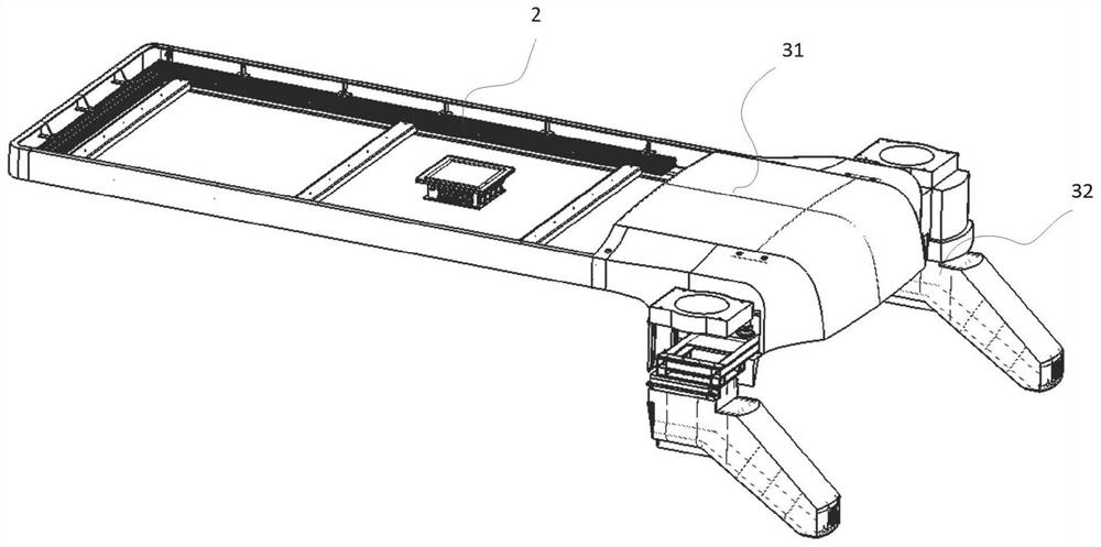
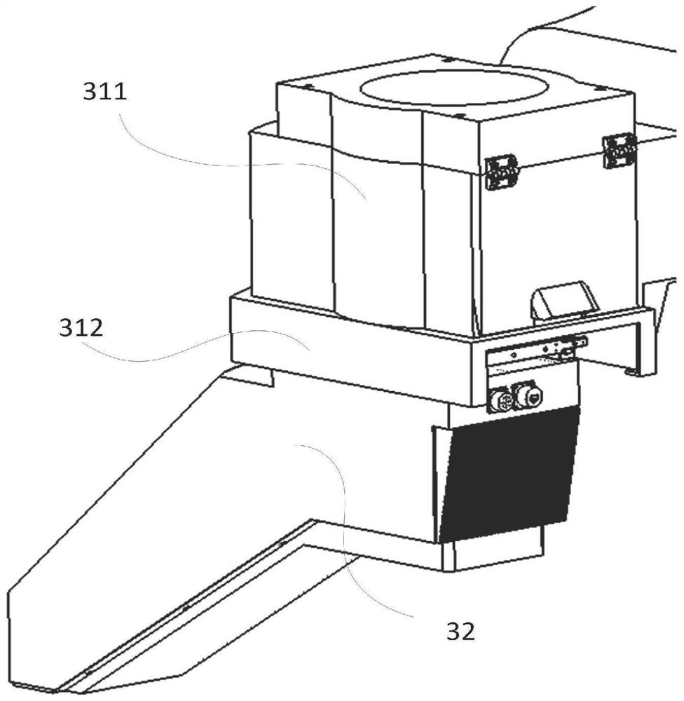
[0048] Such as Figure 1 to Figure 17 As shown, the present embodiment provides a vehicle-mounted road surface detection robot, which includes a detection car 1, a camera module 3 arranged on the top of the detection car 1 for taking images of the ground, arranged on the top of the detection car 1, and connected to the camera The roof frame 2 connected to the module 3, and the ground penetrating radar detection mechanism 4 towed on the detection trolley 1. First of all, it should be noted that the serial numbers such as "first" and "second" in this embodiment are only used to distinguish similar components, and should not be understood as specific limitations on the scope of protection. In addition, directional terms such as "bottom", "top", "surrounding edge", and "center" in this embodiment are described based on the drawings. Not only that, the body structure of the 3D camera in this embodiment belongs to the prior art, and its improvement points lie in the connection posi...


PUM


Abstract

The invention discloses a vehicle-mounted road surface detection robot which comprises a detection trolley, a camera module arranged at the top of the detection trolley and used for shooting images of the ground, and a ground penetrating radar detection mechanism towed on the detection trolley. The ground penetrating radar detection mechanism comprises a ground penetrating radar, an anti-collision guide plate and a ground penetrating radar carrying mechanism, wherein the ground penetrating radar and the anti-collision guide plate are arranged perpendicular to the advancing direction of the detection trolley, and the ground penetrating radar carrying mechanism is connected with the detection trolley, the ground penetrating radar and the anti-collision guide plate. The camera module comprises a camera fixing frame arranged on the top of the detection trolley and two D cameras which are arranged on the two sides of the camera fixing frame in a one-to-one correspondence mode and detachably connected with the camera fixing frame. Through the scheme, the vehicle-mounted road surface detection robot has the advantages of being simple in structure, reliable in action, convenient to connect, good in anti-collision performance and the like, and has very high practical value and popularization value in the technical field of pavement detection.

Description

technical field [0001] The invention relates to the technical field of road surface detection, in particular to a vehicle-mounted road surface detection robot. Background technique [0002] The pavements mentioned in this article include motor vehicle lanes, non-motor vehicle lanes, aircraft take-off and landing lanes, and so on. At present, the vehicle-mounted road surface detection in the prior art mostly uses a detection trolley equipped with a ground-penetrating radar module, although its structure is relatively simple; however, its towed force depends entirely on the trolley. In the actual detection process, the road surface is not completely flat, such as the deceleration mechanism on the motorway, and the road surface has potholes and raised areas. Then, the vehicle-mounted road surface detection robot in the prior art has the problem that the ground penetrating radar module collides with the ground. In addition, the ground-penetrating radar module in the prior art ...

Claims


Application Information

Patent Timeline
Patent Type & Authority Applications(China)
IPC IPC(8): G01S13/88G01S7/02
CPCG01S13/885G01S7/02
Inventor 邓勇军胥健郑斌凌正刚桂仲成
Owner 上海圭目机器人有限公司
Why Eureka
Eureka Blog
Learn More