Method for identifying dynamic coefficient of squeeze film damper
A technology of squeezing oil film damping and identification methods, which is applied in the testing of machines/structural components, testing material strength by applying repetitive force/pulsation force, testing material strength by applying stable tension/pressure, etc., which can solve difficult on-site testing Squeeze oil film damper dynamic coefficient and other issues, to achieve the effect of low cost of experimental equipment, simple calculation, strong engineering
- Summary
- Abstract
- Description
- Claims
- Application Information
AI Technical Summary
Problems solved by technology
Method used
Image
Examples
specific Embodiment approach 1
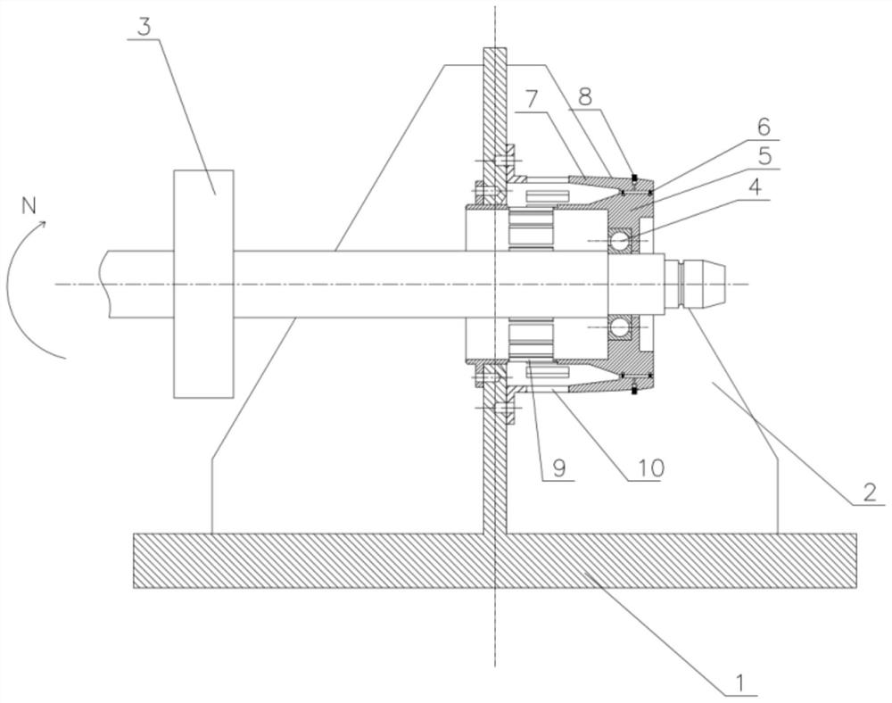
[0090] Specific implementation mode one: refer to Figure 1 to Figure 11 Describe this embodiment, this embodiment provides a kind of identification method of dynamic coefficient of squeeze oil film damper, it is characterized in that: described identification method is realized through the following steps:
[0091] Step 1: Determine the force transmission coefficient K of the elastic squirrel cage support seat in the squeeze film damper in ;
[0092] Step 2: Determine the force transmission coefficient K of the support seat of the damper outer ring in the squeeze film damper out ;
[0093] Step 3: Use the force transmission coefficient K of the elastic squirrel cage support seat obtained in Step 1 in Determine the excitation force F transmitted by the rotor to the elastic squirrel cage support seat when the rotational speed N=nr / min is obtained in | N=n ;
[0094] Step 4: Use the force transmission coefficient K of the damper outer ring support seat obtained in Step 2 ...
specific Embodiment approach 2
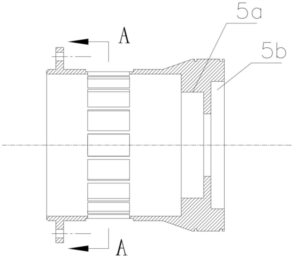
[0096] Specific implementation mode two: refer to Figure 1 to Figure 9 Describe this embodiment, this embodiment is to further limit the step one described in the specific embodiment one, in this embodiment, the force transmission coefficient K of the elastic squirrel cage support seat in the squeeze oil film damper is determined in the step one in Specifically, it is achieved through the following steps:
[0097] Step 11: Install the elastic squirrel cage support seat 5 on the fixing device, and install an elastic squirrel cage support seat for load bearing by interference fit at the installation stop 5b of the elastic squirrel cage support seat bearing plate on the elastic squirrel cage support seat 5 Disc 19, the load-bearing bar 20 is passed in the central through hole of the elastic squirrel cage support seat load-bearing disc 19, and guarantees that the moment arms of the elastic squirrel cage support seat load-bearing disc 19 two ends load-bearing bar 20 are identical;...
specific Embodiment approach 3
[0116] Specific implementation mode three: refer to Figure 1 to Figure 11 Describe this embodiment, this embodiment is to further limit the step 2 described in the second specific embodiment, in this embodiment, the force transmission coefficient K of the damper outer ring support seat in the squeeze oil film damper is determined in the step 2 out Specifically, it is achieved through the following steps:
[0117] Step 21: Install the damper outer ring support seat 7 on the fixing device, and install a damper outer ring with interference fit at the installation stop 7a of the damper outer ring support seat load-bearing plate on the damper outer ring support seat 7 Ring support seat load-bearing plate 24, pass the load-bearing rod 20 through the center through hole of the damper outer ring support seat load-bearing plate 24, and ensure that the moment arms of the load-bearing bars 20 at both ends of the damper outer ring support seat load-bearing plate 24 are the same;
[0118...
PUM
 Abstract
Description
Claims
Application Information
 - Generate Ideas
- Intellectual Property
- Life Sciences
- Materials
- Tech Scout
- Unparalleled Data Quality
- Higher Quality Content
- 60% Fewer Hallucinations
Browse by: Latest US Patents, China's latest patents, Technical Efficacy Thesaurus, Application Domain, Technology Topic, Popular Technical Reports.
© 2025 PatSnap. All rights reserved.Legal|Privacy policy|Modern Slavery Act Transparency Statement|Sitemap|About US| Contact US: help@patsnap.com


