
Safety valve for low-temperature and low-pressure working conditions

A low-temperature, low-pressure, safety valve technology, used in safety valves, lift valves, balance valves, etc., can solve problems such as inappropriateness, low spring preload, and unfavorable surface deformation of sealing blocks, and achieve the effect of solving limited use.

Pending Publication Date: 2021-12-07
BEIJING AEROSPACE PETROCHEM TECH & EQUIP ENG CORP LTD
View PDF5 Cites 1 Cited by
  • Summary
  • Abstract
  • Description
  • Claims
  • Application Information

AI Technical Summary

Problems solved by technology

[0003] Due to the particularity of the medium, it is necessary to ensure that the safety valve has no leakage, and the metal sealing form cannot meet the leakage rate requirements of the working conditions, so a soft sealing form is required to achieve zero leakage;
[0004] Under low temperature conditions, the rubber material of the O-ring has poor cold resistance, and it will harden at low temperatures, which will affect its sealing performance and service life, so it is not suitable to use the O-ring sealing form; under low pressure conditions, the spring The pre-tightening force is low, which is not conducive to the deformation of the surface of the sealing block, and cannot achieve effective sealing with the valve seat, so the sealing form of the sealing block is not suitable

Method used


Image

  • Safety valve for low-temperature and low-pressure working conditions

Examples


Embodiment Construction

[0023] In order to solve the problem of low temperature and low pressure working conditions such as liquid nitrogen storage tanks, it is not suitable to use commonly used metal seals, seal block seals and O-ring seals. The safety valve provided by the embodiment of the present invention has the following characteristics:

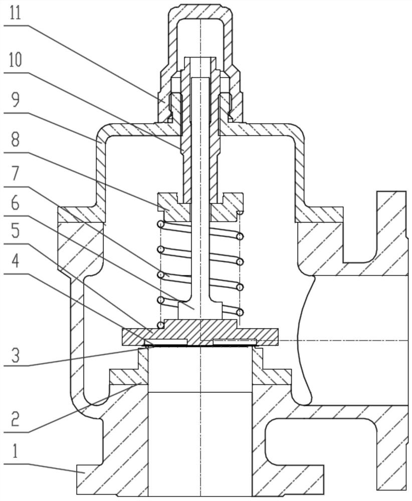
[0024] Brand-new sealing structure: the seal between the valve seat and disc adopts FEP diaphragm soft sealing structure, FEP material can withstand low temperature conditions, and the FEP diaphragm structure still has good ductility guarantee under low pressure, ensuring low temperature and low pressure The sealing performance of the safety valve under working conditions.

[0025] Lightweight internal structure: the lower spring seat is integrated with the valve disc, and the valve stem and adjusting screw are used for guiding structure, which cancels the traditional guiding parts, makes the structure of the whole valve more compact, realizes the light weigh...


PUM

PropertyMeasurementUnit
Thicknessaaaaaaaaaa

Abstract

The invention discloses a safety valve for low-temperature and low-pressure working conditions. The safety valve comprises a valve body, a valve seat, a diaphragm, a valve clack, a spring and an upper spring seat, the valve body is of a cavity structure with the two ends being solid parts and the middle being hollow, one end of the valve seat is connected with the solid parts of the valve body, the other end of the valve seat is in contact with one end of the diaphragm, the other end of the diaphragm is fixedly connected with the valve clack, the spring is arranged at the end, away from the diaphragm, of the valve clack, and the spring is arranged between the valve clack and the upper spring seat. When a system pressure reaches the set pressure, the valve clack drives the spring to move towards the side away from the valve body, the diaphragm is separated from the valve body, sealing of the cavity structure is relieved, and therefore a medium is discharged from an outlet of the valve body. When the system pressure is reduced to a return pressure, the valve clack drives the spring to move towards one side of the valve body, and the diaphragm makes contact with the valve body so as to seal the outlet of the valve body. The purpose that the whole valve is free of leakage under the low-temperature and low-pressure working conditions can be achieved.

Description

technical field [0001] The invention relates to the technical field of safety valve design, in particular to a safety valve used in low-temperature and low-pressure working conditions. Background technique [0002] At present, pressure relief devices are widely used in various sectors of the national economy such as petroleum, chemical industry, power station, metallurgy, nuclear power, and national defense. With the improvement of production efficiency, relevant departments and enterprises have increasingly stringent requirements on environmental protection and safety. As an essential part of the emergency relief system, the performance and sealing requirements of the pressure relief device providing overpressure protection are also more stringent. Taking the liquid nitrogen storage tank system as an example, the system is a low-temperature and low-pressure working condition, the temperature is as low as -196°C, and the pressure is lower than 0.1MPa. At present, the common...

Claims


Application Information

Patent Timeline
IPC IPC(8): F16K17/04F16K1/36
CPCF16K17/04F16K17/0413F16K1/36
Inventor 汪朝阳鲍鲜宇郭善刚张翔宇边玲王学彬李晓峰
Owner BEIJING AEROSPACE PETROCHEM TECH & EQUIP ENG CORP LTD
Learn More