


Quick Research
Generate reliable direction feasibility study reports for your R&D in just a few steps.

Technical Q&A
Discover and master advanced knowledge NOW. Basics, ideas, possibilities, all at once.

Find Solutions
As an expert in R&D theories, this can generate solutions to your technical problems instantly.

Evaluate Feasibility
Analyze your overall solution with one click, know your potential R&D risks in advance.

Monitor Landscape
Get weekly tech updates, stay abreast of the latest tech innovations and key insights.
Device for installing air pipe in narrow vertical shaft and hoisting method
A hoisting method and the technology of the inner air duct, which are applied in hoisting devices, hoisting equipment braking devices, transportation and packaging, etc., can solve the problem of difficult sealing at the flange of the air duct connected to the insulation floor of the air duct, and the gap between the duct well and the duct It can solve problems such as tight space and achieve the effect of improving installation efficiency and reliability
- Summary
- Abstract
- Description
- Claims
- Application Information
AI Technical Summary
Problems solved by technology
Method used
Image


Examples
Embodiment 1
[0034] In view of the low efficiency of installing air ducts in the prior art, cumbersome procedures, and time-consuming and labor-intensive installation of the narrow structure of the air shaft, this embodiment is optimized to solve the problems existing in the prior art.
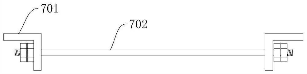
[0035] Specifically, such as figure 1 As shown, this embodiment provides a device for installing air ducts in narrow shafts, including a main bracket, which is arranged at the air duct well and is connected and fixed with the inner wall and the ground of the building; the main bracket is provided with a lifting Device 3, the hoisting device 3 is connected to the hoop device 7 through the hoisting cable 6, and the hoop device 7 is used to hold the upper port of the air duct section tightly and drive the air duct section up and down under the action of the hoisting device 3; the hoop device 7 includes a set of holding side bars 701 oppositely arranged, and at least two pair of tie rods 702 for adjusting the ...
Embodiment 2
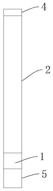
[0045] This embodiment discloses a device for installing an air duct in a narrow shaft. The difference from Embodiment 1 is that this embodiment optimizes the top beam structure.
[0046] Specifically, such as Figure 4 As shown, the present embodiment adopts another kind of feasible roof beam structure 2: the roof beam structure 2 is a U-shaped beam structure, the middle part of the U-shaped beam is connected and fixed with the column 1, and the two ends of the U-shaped beam are connected with the column 1. Internal wall connections are fixed. When such a solution is adopted, the U-shaped beam structure has two supporting structures, both of which can be used to install the lifting device 3 to increase the lifting force. If the two lifting devices 3 are installed together for lifting, the stability and safety of the lifting can be effectively improved sex.
[0047] Other structural components not mentioned in this embodiment are the same as those in Embodiment 1, and will n...
Embodiment 3
[0049] The content of the above-mentioned embodiment 1 describes the hoisting device, and this embodiment discloses the corresponding hoisting method, which is now described as follows:
[0050] Such as Figure 5 As shown, a hoisting method for the installation of air ducts in narrow shafts, including:
[0051] S01: Assemble and connect the air duct section into an air duct section, and move the air duct section to the air shaft, and complete the installation of the bottommost air duct section;
[0052] S02: Install the upper and lower sections of the air duct at the air shaft of each floor, and install them layer by layer from the bottom to the top; connect the hoop device with the upper section of the air duct on this floor, and use the lifting device to lift the floor The upper section of the air duct is hoisted into the air shaft;
[0053] S03: Use the lifting device to lift the upper air duct section of the floor to a certain distance, and at the same time put the lower...
PUM
 Abstract
Description
Claims
Application Information
 - R&D Engineer
- R&D Manager
- IP Professional
- Industry Leading Data Capabilities
- Powerful AI technology
- Patent DNA Extraction
Browse by: Latest US Patents, China's latest patents, Technical Efficacy Thesaurus, Application Domain, Technology Topic, Popular Technical Reports.
© 2024 PatSnap. All rights reserved.Legal|Privacy policy|Modern Slavery Act Transparency Statement|Sitemap|About US| Contact US: help@patsnap.com