
Tool locking ram structure of turning and milling composite equipment

A technology of compound equipment and ram, which is applied in the field of tool locking ram structure of turning and milling compound equipment, can solve the problems of time-consuming, troublesome process, and inability to guarantee the quality and precision of parts processing, so as to reduce the number of clamping and improve the Production efficiency, the effect of reducing production assistance time

Active Publication Date: 2021-12-07
浙江日发精密机床有限公司
View PDF12 Cites 0 Cited by
  • Summary
  • Abstract
  • Description
  • Claims
  • Application Information

AI Technical Summary

Problems solved by technology

[0003] Aiming at the problem that the existing parts are complicated due to multiple clamping, the replacement process is not only time-consuming, but also the processing quality and precision of the parts cannot be guaranteed, the present invention aims to provide a tool locking ram structure for turning and milling compound equipment

Method used


Image

  • Tool locking ram structure of turning and milling composite equipment
  • Tool locking ram structure of turning and milling composite equipment

Examples


Embodiment Construction

[0016] Specific embodiments of the present invention will be described in detail below in conjunction with the accompanying drawings.

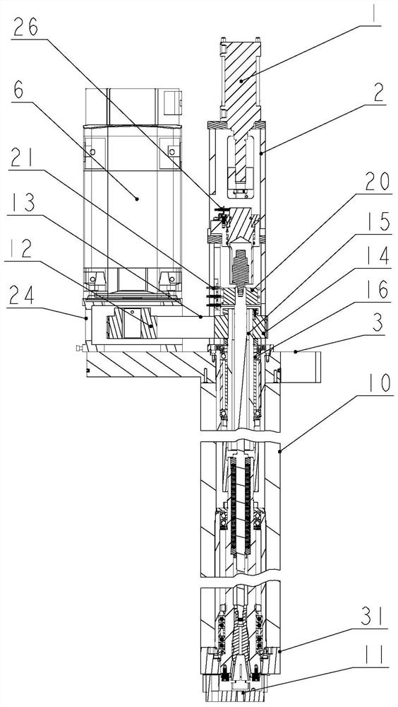
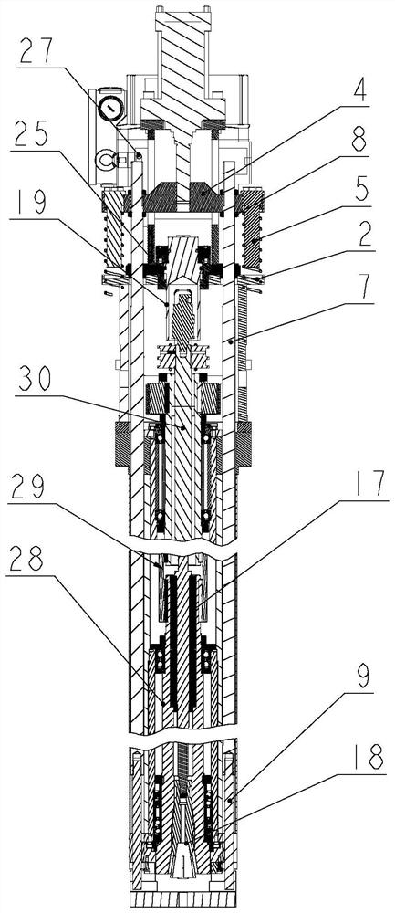
[0017] Such as Figure 1-Figure 2 As shown, the turning tool oil cylinder 1 is installed on the fixed seat 2, the fixed seat 2 is installed on the fixed plate 3, and the fixed plate 3 is fixed on the upper end of the ram 10; the turning tool oil cylinder 1 piston is connected with the support 4, and the two sides of the support 4 The pull rod 7 is fixed by the lock nut 8, the limit rod 5 is fixed on the outside of the support 4; one end of the T-shaped clamp rod 9 is fixed with the pull rod 7; the T-shaped clamp rod 9 is connected with the T-shaped groove of the turning tool holder 11; the induction switch 27 Installed on the bracket 2, it is used to monitor the position of the pull rod 7.

[0018] The motor 6 is installed on the motor base 24, and the motor base 24 is installed on the fixed plate 3; the first pulley 12 is installed on the ou...


PUM


Abstract

The invention discloses a tool locking ram structure of turning and milling composite equipment, and belongs to the technical field of machine tool cutter component devices. The problems that due to the fact that an existing part is clamped many times, the working procedure is troublesome, time is consumed in the replacement process, and the machining quality and precision of the part cannot be guaranteed are solved. The tool locking ram structure comprises a turning tool loosening and tightening mechanism, a milling cutter loosening and tightening mechanism, a main shaft rotating mechanism and a ram. The tool locking ram structure has the advantages of being compact in structure, reliable in operation and the like, and solves one core problem of turning and milling combination of a machine tool. When applied to a machine tool, the turning and milling combination can be realized, the part clamping frequency is reduced, and the part machining precision is greatly improved. The tool locking ram structure can be used in cooperation with a tool magazine, tool loading and unloading automation is achieved, and the automation degree of equipment is further improved. In this way, due to the automation of tool replacement, the production auxiliary time is shortened, and the production efficiency can be obviously improved.

Description

technical field [0001] The invention belongs to the technical field of tool component devices for machine tools, and in particular relates to a tool locking ram structure for turning and milling compound equipment. Background technique [0002] In mechanical cutting processing, turning and milling are two different processing methods, which are generally completed by lathes and milling machines respectively. For example, turning and milling combined processing is to realize two different processing technologies on one machine tool. The turning-milling machine tool is equivalent to a combination of a CNC lathe and a milling machine. In this process, the parts are troublesome due to multiple clamping, and the replacement process is not only time-consuming, but also leads to the inability to guarantee the processing quality and precision of the parts. Contents of the invention [0003] Aiming at the problem that the existing parts are complicated due to multiple clamping, t...

Claims


Application Information

Patent Timeline
IPC IPC(8): B23Q3/00B23P23/02
CPCB23Q3/00B23P23/02
Inventor 何晓峰张小雨吕彭晖王越锋孙敏敏
Owner 浙江日发精密机床有限公司
Learn More