Valve grease injection tool
A technology of grease injection and tools, which is applied to the device and coating of the surface coating liquid, which can solve the problem of inability to adjust the grease injection flow rate, monitor the grease injection pressure, complex structure and operation process of the grease injection tool, and affect the sealing grease lubrication Effect and other issues, to achieve the effect of good reliability, reduce the number of parts and expand the scope of application
- Summary
- Abstract
- Description
- Claims
- Application Information
AI Technical Summary
Problems solved by technology
Method used
Image

Examples
Embodiment 1
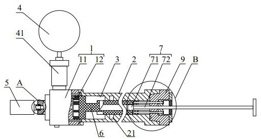
[0035] like Figure 1-9As shown, a valve grease injection tool includes a confluence mechanism 1 and a grease injection cylinder 2 that are rotatably connected. Several flow channels are arranged in the confluence mechanism 1. The confluence mechanism 1 includes a confluence head 11 and an orifice plate 12. The orifice plate 12 is detachably connected to the confluence head 11, the orifice plate 12 is provided with a plurality of through holes 121 with different apertures, the confluence head 11 is provided with a channel 111, and the through hole 121 is connected to the channel 111 to form the flow path, the grease injection cylinder 2 is provided with a grease injection channel 3, the grease injection channel 3 is provided with a flow regulator 6, and the flow regulator 6 is provided with a The selection hole 63 communicated with the flow channel, coaxially rotate the confluence mechanism 1 and the grease injection cylinder 2, the selection hole 63 can communicate with the s...
Embodiment 2
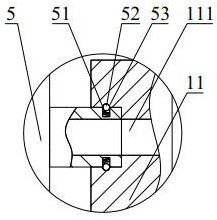
[0046] like Figure 1-9 As shown, a valve grease injection tool in this embodiment has the same structure as that in Embodiment 1, except that the grease injection head 5 can be engaged with the confluence mechanism 1 .
[0047] In this embodiment of a valve grease injection tool, the snap connection is a quick connection structure realized by the cooperation of the elastic member 51, the ball 52 and the chute 53. Since the grease injection head 5 and the confluence mechanism 1 are snap connected, the change The threaded connection mode of the grease injection head 5 in the original grease injection tool can be realized, and the rapid assembly, disassembly and replacement of the grease injection head 5 can be realized, and the operation process is further simplified.
Embodiment 3
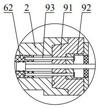
[0049] like Figure 1-9 As shown, a valve grease injection tool of this embodiment has the same structure as that of Embodiment 2, the difference is that: the inner wall of the grease injection cylinder 2 is provided with a ring groove 21, and the ring groove 21 corresponds to the grease injection cylinder 2 A first auxiliary channel 22 is provided inside, and the first auxiliary channel 22 is used to connect an external liquid supply mechanism or an air supply mechanism or a grease injection mechanism. The communication groove 66 of the above-mentioned grease injection channel 3.
[0050] In the valve grease injection tool of this embodiment, preferably, the annular groove 21 is set in the second channel 31 of the grease injection channel 3, and the communication groove 66 is set on the adjustment rod 62, so that the operating mechanism 9 When the flow regulator 6 is driven to move along the grease injection channel 3 until the communication hole 65 communicates with the rin...
PUM
 Abstract
Description
Claims
Application Information
 - R&D
- Intellectual Property
- Life Sciences
- Materials
- Tech Scout
- Unparalleled Data Quality
- Higher Quality Content
- 60% Fewer Hallucinations
Browse by: Latest US Patents, China's latest patents, Technical Efficacy Thesaurus, Application Domain, Technology Topic, Popular Technical Reports.
© 2025 PatSnap. All rights reserved.Legal|Privacy policy|Modern Slavery Act Transparency Statement|Sitemap|About US| Contact US: help@patsnap.com