Explosion-proof motor stator paint dipping device
An explosion-proof motor and varnish impregnation technology, which is applied in electromechanical devices, manufacturing motor generators, electrical components, etc., can solve the problems of insulating varnish waste, large stator shape, dense coils and insulating paper, etc., to increase penetration efficiency and reduce use , the effect of improving efficiency
- Summary
- Abstract
- Description
- Claims
- Application Information
AI Technical Summary
Problems solved by technology
Method used
Image


Examples
Embodiment 1
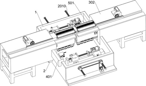
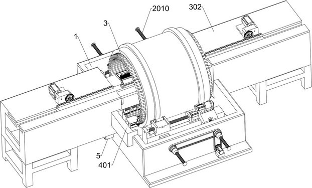
[0040] An explosion-proof motor stator impregnation device, such as Figure 1-2 As shown, it includes a supporting drive assembly, an auxiliary soaking assembly, a paint dipping tank 1 and a paint discharge pipe 2; the paint discharge pipe 2 is fixedly connected to the lower left part of the paint dipping tank 1; the front and rear sides of the inner wall of the dipping tank 1 are respectively A support drive assembly is installed, and the two support drive assemblies are symmetrically arranged; an auxiliary wetting assembly is respectively installed on the left and right sides of the dipping tank 1, and the two auxiliary wetting assemblies are symmetrically arranged; the two support drive assemblies A kilowatt-level stator 3 is placed between the upper parts of the components, and the combined components of the two auxiliary wetted components are located inside the kilowatt-level stator 3 .
[0041] During processing, the insulating varnish is sucked into the dipping pool 1 f...
Embodiment 2
[0043] On the basis of Example 1, such as figure 1 and Figure 3-11 As shown, the auxiliary wetting assembly on the right includes a bottom frame 301, a hollow sliding sleeve 302, a second L-shaped base 303, a first gear 304, a cross-shaped slider 305, a rack 306, a first fixed frame 307, a second Two telescopic parts 308, controller 309, connection block 3010, circular plate 3011, connecting rod 3012, third telescopic part 3013, fourth telescopic part 3014, U-shaped frame 3015, round rod 3016, ring 3017, elastic part 3018, Folding soft board 3019, first bristles 3020, block 3021, fourth drive member 3022, sixth synchronous wheel 3023, fourth synchronous belt 3024, bearing plate 3025, three-leaf paddle rod 3026, folding plate 3027, seventh synchronous wheel 3028 and the fifth driving member 3029; the right part of the dipping tank 1 is connected with a hollow sliding sleeve 302, and the bottom of the hollow sliding sleeve 302 is connected with a chassis 301; the middle part o...
Embodiment 3
[0055] On the basis of Example 2, such as figure 1 and Figure 13-14 As shown, it also includes an effusion separation assembly. The left front part of the upper surface of the dipping tank 1 is fixedly connected with an effusion separation assembly. Plate 404, the sixth driving member 405, the second gear 406, the third gear 407, the rotating shaft rod 408, the gear chain group 409, the first positioning rod 4010, the positioning plate 4011, the limit slip ring 4012, the second positioning rod 4013 and The brush 4014; the left front part of the upper surface of the dipping tank 1 is fixedly connected with a side casing 401; the inner left wall of the side casing 401 is fixedly connected with an electric slide rail 402; the right side of the sliding block of the electric slide rail 402 is connected with a fixed rod 403; the right end of the fixed rod 403 is rotatably connected with a U-shaped plate 404; the right front portion of the upper surface of the U-shaped plate 404 is...
PUM
 Abstract
Description
Claims
Application Information
 - R&D
- Intellectual Property
- Life Sciences
- Materials
- Tech Scout
- Unparalleled Data Quality
- Higher Quality Content
- 60% Fewer Hallucinations
Browse by: Latest US Patents, China's latest patents, Technical Efficacy Thesaurus, Application Domain, Technology Topic, Popular Technical Reports.
© 2025 PatSnap. All rights reserved.Legal|Privacy policy|Modern Slavery Act Transparency Statement|Sitemap|About US| Contact US: help@patsnap.com